Chapter 4
System Setup
41
Procedure
Perform the following procedure to mount the Adjustable C- to Spectroscopy-Mount
adapter:
1. If a light baffle is mounted to the front of the adapter, remove the two 2-56 screws
securing it and set the baffle aside.
2. Orient the adapter with the setscrew at the top and, using a spanner wrench or
equivalent (distance between holes is 1.17 inch [29.7 mm]), tighten the threaded
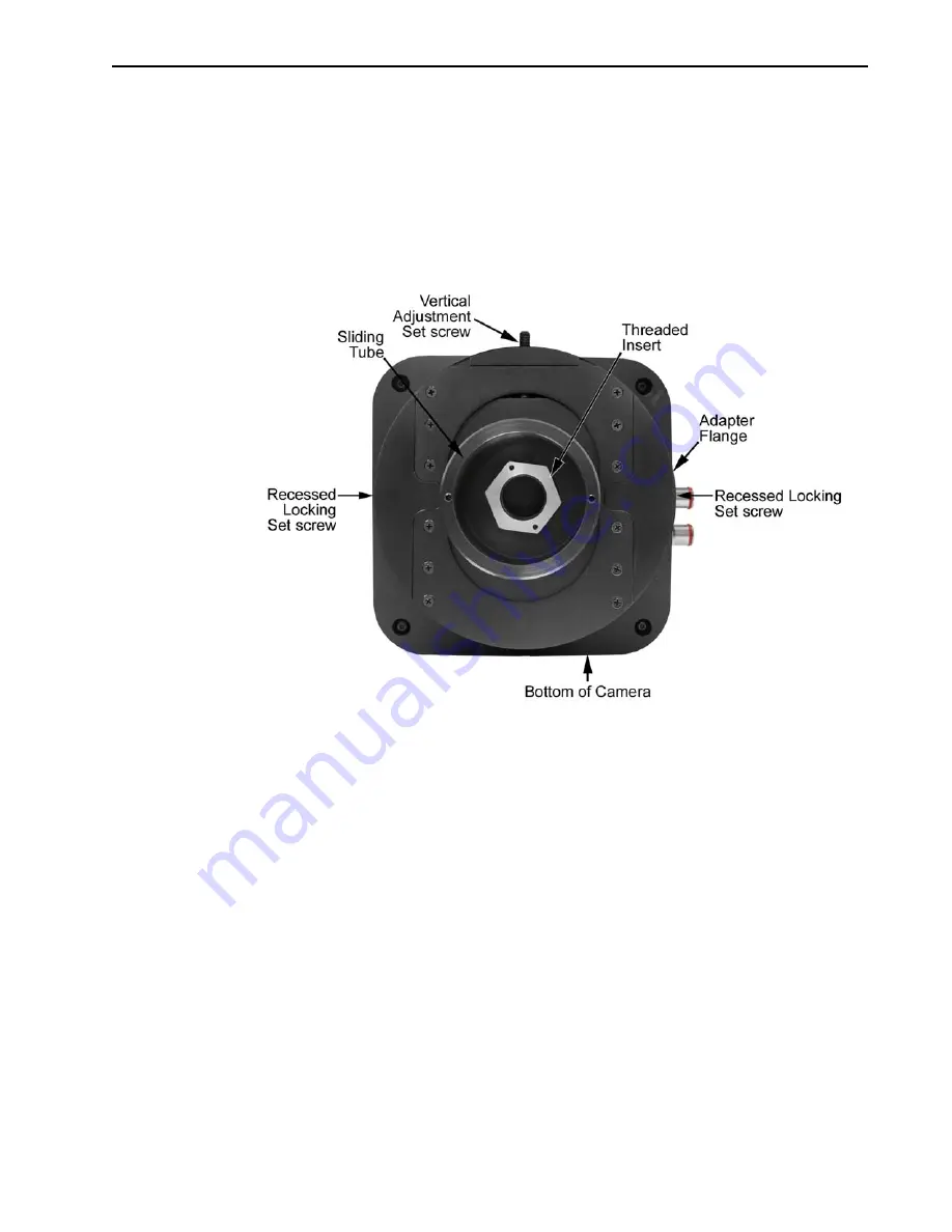
insert into the C-mount opening on the camera. See
Figure 4-2: Typical Adjustable C- to Spectroscopy-Mount Adapter
3. If you are using a light baffle, mount the light baffle to the front of the adapter.
4. Gently rotate the camera and sliding tube assembly as you insert it into the
spectrograph’s exit port.
5. With the spectrograph, camera, and light source powered on and connected to the
computer (as required), start the application software. Refer to the appropriate First
Light instructions in this manual when focusing and rotationally aligning the camera
to the spectrograph optics.
6. When you have finished with focusing and rotational alignment, secure the sliding
tube in place with the spectrograph set screws.
7. If they have already been installed, loosen the adapter’s two recessed locking
setscrews (use a 0.050 inch hex key). If they have not been installed, insert the
setscrews into the holes at the sides of the adapter and screw them in a couple of
turns.
8. When the camera opening is centered within the sliding tube, you can adjust the
camera up or down 0.4 inch [4.06 mm] by tightening or loosening the vertical
adjustment setscrew (use a 3/32 inch hex key).
9. After you have completed the adjustment, tighten the recessed locking setscrews in
the adapter flange to lock the position.
4
4
11
-01
26
_
0017
Summary of Contents for ProEM Series
Page 1: ...www princetoninstruments com ProEM System Manual 4411 0126 Issue 3 September 26 2019 ...
Page 10: ...10 ProEM System Manual Issue 3 This page is intentionally blank ...
Page 16: ...16 ProEM System Manual Issue 3 This page is intentionally blank ...
Page 30: ...30 ProEM System Manual Issue 3 This page is intentionally blank ...
Page 50: ...50 ProEM System Manual Issue 3 This page is intentionally blank ...
Page 88: ...88 ProEM System Manual Issue 3 This page is intentionally blank ...
Page 114: ...114 ProEM System Manual Issue 3 This page is intentionally blank ...
Page 122: ...122 ProEM System Manual Issue 3 Figure 7 8 LightField Settings 4411 0126_0078 ...
Page 136: ...136 ProEM System Manual Issue 3 This page is intentionally blank ...
Page 146: ...146 ProEM System Manual Issue 3 This page is intentionally blank ...
Page 152: ...152 ProEM System Manual Issue 3 This page is intentionally blank ...
Page 161: ...This page is intentionally blank ...


