background image

RCPF-1000 Fiber Optic System Controller 

209872 REV - 

57 

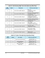
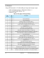
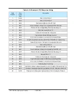
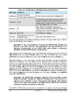
Table 6-8:  System Condition Addressing (Read Only) 

1 2 

Present DAC value 

(Read Only in Temp Co Mode) 

0 to 1023 

Present Temperature 

+ 125 

Fault, Mute, and State Conditions 

2-Byte Value 

0 fault clear;  1 fault set 

0 mute clear; 1 mute set 

0 standby state, 1 on line state 


Lower Byte


Bit 0 = Summary Fault 
Bit 1 = High Temp Fault 
Bit 2 = Low DC Current Fault 
Bit 3 = Low DC Voltage Fault 
Bit 4 = External Mute Status 
Bit 5 = Internal Mute Status 
Bit 6 = Reserved, always 0 
Bit 7 = Reserved, always 0 
  

High Byte


Bit 0 = Block Up Converter Fault 
Bit 1 = Spare Fault 
Bit 2 = Auxiliary Fault 
Bit 3 = Fiber RX Link Fault 
Bit 4 = RF Switch Control 1 state 
Bit 5 = RF Switch Control 2 state 
Bit 6 = Reserved, always 0 
Bit 7 = Unit On Line State 

Present Attenuation Level 

1bit per 0.1 dB attenuation 

Low Byte: 0 to 200 

High Byte: always 0 

5 2 

Present RF Power Level 

Output is dBm x 10 

Ie 455 = 45.5 dBm 

0 to 1023 

SSPA DC Current 

200 Amp maximum 

1 value = 0.1 Amp 

7 2 

Regulator 

DC 

Voltage 

15 Volt maximum 
1 value = 0.1 Volt 

Power Supply Voltage 

15 Volt maximum 
1 value = 0.1 Volt 

Transistor Gate Voltage 

0 to 10 volt range 

Use 2’s compliment integer math 

1 value = 0.1 Volt 

Note: This table is common for both RCP2-1000 and Compact Outdoor SSPA and will not change 
when the device type is switched. 

Data 

Address


# Bytes


Description


Limits and Byte Values


Summary of Contents for RCPF-1000-CO

Page 1: ...nual For use with Compact Outdoor SSPAs with Fiber Interface 209872 REV RA 6287 10 11 2012 Teledyne Paradise Datacom LLC Phone 814 238 3450 328 Innovation Blvd Suite 100 Fax 814 238 3829 State College...

Page 2: ...A United Kingdom 814 238 3450 switchboard 44 0 1376 515636 814 238 3829 fax 44 0 1376 533764 fax Information in this document is subject to change without notice The latest revision of this document m...

Page 3: ...N F 15 2 2 2 RX IFL Connector J22 Type N F 15 2 2 3 Power Alarm Connector J23 MS3112E10 6P 16 2 2 4 OPT TX RX Connector J24 Amphenol 956 220 5000 R 16 2 3 Optional OFM 1000 Antenna Boom Mounting Kit 1...

Page 4: ...1 3 Sys Info Page 3 31 4 2 1 4 Sys Info Page 4 31 4 2 1 5 Sys Info Page 5 31 4 2 1 6 Sys Info Page 6 32 4 2 1 7 Sys Info Page 7 32 4 2 1 8 IP Info Page1 33 4 2 1 9 IP Info Page 2 33 4 2 1 10 IP Info...

Page 5: ...Overview 45 6 1 Serial communication 46 6 1 1 Header Packet 46 6 1 1 1 Frame Sync Word 47 6 1 1 2 Destination Address 47 6 1 1 3 Source Address 47 6 1 2 Data Packet 47 6 1 2 1 Protocol ID 47 6 1 2 2...

Page 6: ...2 Fiber Optic Cable Run Considerations 87 7 2 1 Why use SC UPC optical connectors 88 7 2 2 Connector maintenance 88 7 2 3 Attenuation vs Optical Loss 88 7 2 4 Estimating maximum fiber length 89 7 3 IF...

Page 7: ...Figure 4 2 Main Menu Initial Menu Selection 29 Figure 4 3 RCPF 1000 System Information IPInfo and Version Info Menus 30 Figure 4 4 Panel Com Menu 34 Figure 4 5 SSPA Setup Menu 36 Figure 4 6 Panel Setu...

Page 8: ...Table 6 2 Data Tag Byte Values 49 Table 6 3 Error Status Byte Values 50 Table 6 4 Request Frame Structure 54 Table 6 5 Response Frame Structure 54 Table 6 6 System Settings Data Values for Compact Out...

Page 9: ...r fiber optics The optical link is achieved by direct amplitude modulation of the laser at L Band Demodulation occurs at the receiver utilizing a photo diode detector The optical link is designed to p...

Page 10: ...resistant enclosure the OFM 1000 The RCPF 1000 connects via two fiber optic cables to the OFM 1000 L Band coaxial cables connect the SSPA and the LNB to the OFM 1000 Figure 1 1 shows a block diagram o...

Page 11: ...ied The following equipment is supplied with units using a fiber optic interface SSPA with integral ZBUC converter OFM 1000 external Fiber Optic enclosure RCPF 1000 Remote Control Panel 1 IEC Line Cor...

Page 12: ...rture 0 14 Laser Radiation can damage your eyes Do not look directly into the fiber terminations The system uses WDMs therefore all fibers radiate optical power All optical connectors must be polished...

Page 13: ...losure This interface allows connection between a SSPA with integrated ZBUC converter and an indoor RCPF 1000 Remote Control Panel Figure 2 1 shows an outline of an External Fiber Optic Interface Figu...

Page 14: ...a light source with a narrow spectral width thus reducing any distortion resulting from overlapping light pulses and providing the least signal attenuation and the highest transmission speeds of any...

Page 15: ...ernal L band to fiber transceiver 2 2 1 TX IFL Connector J21 Type N F Connects to the RF IN port J1 of a SSPA using a properly terminated IFL cable 2 2 2 RX IFL Connector J22 Type N F Connects to the...

Page 16: ...he system is in operation Doing so will damage the internal laser assembly 2 2 4 OPT TX RX Connector J24 PT LC Amphenol 956 220 5000 R Connects to the RCPF 1000 Fiber TX Port J21 and Fiber RX Port J22...

Page 17: ...Optional OFM 1000 Antenna Boom Mounting Kit An optional machined aluminum mounting plate is available for the purpose of mounting the OFM 1000 to an antenna boom See Appendix D for instructions for at...

Page 18: ...18 209872 REV RCPF 1000 Fiber Optic System Controller THIS PAGE LEFT INTENTIONALLY BLANK...

Page 19: ...c Control Panel Overview The RCPF 1000 Fiber Optic Control Panel is a 1RU rack mountable controller for use with a Teledyne Paradise Datacom Compact Outdoor Solid State Power Amplifier with an externa...

Page 20: ...48V DC input 3 2 1 1 AC Power J1 IEC F socket connector The RCPF 1000 Fiber Optic Control Panel features a removable AC power supply module with connector J1 provided on the rear panel The AC input c...

Page 21: ...B9 female connector serves as primary remote control interface connector This interface allows the user to connect a PC to the RCP unit in order to access its advanced features as well as access a rem...

Page 22: ...tor A DB25 male connector is used to provide in the field flash re programmability for the RCP controller card In order to reload controller board firmware connect this port to a PC Parallel port via...

Page 23: ...l interface when the Interface option is selected to IPNet as described in Section 3 5 2 2 This feature allows the user to connect the RCP to a 10 100 Base T office Local Area Network and have full fe...

Page 24: ...ture Fault Form C Relay NO 26 High Temperature Fault Common 9 1 Standalone mode Closed on Regulator Low Voltage Fault 2 1 1 Redundancy Mode Closed on HPA Standby Form C relay NC 27 1 Standalone Mode O...

Page 25: ...door fiber optic transceiver This link also provides 10MHz reference to the outdoor hardware 3 2 8 IFL Out J22 N type connector This connector provides the receive downlink L Band output to the modem...

Page 26: ...26 209872 REV RCPF 1000 Fiber Optic System Controller THIS PAGE LEFT INTENTIONALLY BLANK...

Page 27: ...f the front panel reflect some of the SSPA major faults plus summary fault state The LED on the mimic panel will turn green when the SSPA is in Online mode 1 1 Mode or serves as an AC power indicator...

Page 28: ...ain menu No matter what menu screen is currently displayed on the VFD pressing this key returns the user to the main menu eliminating the need to scroll backward through several menu levels See Sectio...

Page 29: ...will display the attenuation adjustment screen Press Enter to return to the first informative page The user can also browse between these pages by pressing the enter button on the keypad Note this fun...

Page 30: ...PInfo and Version Info Menus Sys Info Atten dB XX X RFOut dBm Watts XX X Alarms XXXXXX Temp C XX X Voltage XXXXXX Temperature XXXXXX Current XXXXXX Low RF XXXXXX BUC XXXXXX Int Mute XXX State XXXXXX A...

Page 31: ...l of the HPA If the HPA is muted the current drops to a 0 to 5 A range which is normal Regul V voltage regulator output Normally this value should read close to 10V if not muted and close to 0V if mut...

Page 32: ...old for cold standby HPA always mutes itself in standby mode and unmutes when switched back on line RFSW Shows the state of the external wave guide path redundancy switch Possible values Normal and Fa...

Page 33: ...0 LockIP This address is used to increase the security measure for the IPNet protocol The SSPA will answer a request which comes only from a specified IP address Set this address value to 0 0 0 0 or 2...

Page 34: ...Page 2 version 4 0 This page provides additional SSPA information including the Digital Core Board version and the date of manufacture 4 2 2 Panel Com Menu This Menu allows the user to select the par...

Page 35: ...ffective immediately Changes to these parameters from serial interface require that the unit be reset in order to take effect The units can be reset either by cycling power to the unit or by issuing a...

Page 36: ...SSPA as the standby HPA in a redundant system 4 2 3 3 Mute Allows the user to mute or unmute the remote SSPA 4 2 3 4 SSPAID Provides information about the type of the Remote SSPA as well as its seria...

Page 37: ...on the Remote SSPA 4 2 4 3 LowRF Provides access to local low RF Fault settings Menu allows enabling or disabling of the low RF fault and setting its threshold level 4 2 4 4 Control Allows the user t...

Page 38: ...es saved settings either those from a previous backup User or to those as shipped from the factory Factory 4 2 5 3 Lamptest This selection activates all LED indicators on the front panel including the...

Page 39: ...es are Low Medium and High 4 2 6 LNB Calibration Menu This menu makes available functions to backup or restore settings set a password or the brightness of the LCD and test the LED lamps on the front...

Page 40: ...d for the LNB if equipped This value is stored on the SSPA Figure 4 9 shows a representative display of this menu choice 4 2 6 2 Re Calibrate This screen allows the user to recalibrate low and high LN...

Page 41: ...Spectrum Analyzer or Power Meter Crossguide coupler Waveguide Load Reference Diplexer Reference Oscillator Loop Test Translator 5 2 Uplink TX Path Verification Refer to Figure 5 1 for a block diagram...

Page 42: ...utput Using the provided coaxial cable connect the LNB L Band output to the OFM 1000 J22 RX IFL input Terminate the LNB RF input waveguide input using an appropriate waveguide to coaxial adapter Conne...

Page 43: ...tem Monitor this port using the Spectrum analyzer Receive power can also be monitored on the modem front panel Once the system has been verified to be operating according to specification a BER test c...

Page 44: ...Com 2 Fiberlink 6 Fiberlink On 2 Make sure your modem is set up at the proper transmit frequency and output power with the carrier enabled and with the following BUC settings BUC Type Other BUC Refere...

Page 45: ...erface provides the ability to control the system through IPNet interface UDP encapsulated Normal Compact Outdoor serial protocol Section 6 4 2 SNMP V1 Section 7 4 3 or HTTP Web interface Section 6 4...

Page 46: ...pe switch tag needs to be set appropriately Refer to Section 6 1 5 Multiple Device Access for more information 6 1 Serial communication This section describes the normal communication protocol between...

Page 47: ...1000 unit will reply with its unique address 6 1 1 3 Source Address The source address specifies the address of the node that is sending the packet All unique addresses except the broadcast address a...

Page 48: ...response frame The length of the Get Response frame varies by the amount of attached data bytes It may contain 11 N bytes where N is the amount of requested data bytes from a particular table specifie...

Page 49: ...lues Tag Name Data Tag Byte Value Minimum valid length of the Data Field Description System Settings Tag 0 1 Byte This tag allows accessing various system settings on remote unit Host access status Fu...

Page 50: ...ced in this field The Get Request type of command must not contain any Data Field Get Request will be rejected if any data is present in the Data Field Generally the Bad Checksum error code will be ad...

Page 51: ...cksums are generated by summing the value of each byte in the packet while ignoring any carry bits A simple algorithm is given as Chksum 0 FOR byte_index 0 TO byte_index packet_len 1 Chksum chksum BYT...

Page 52: ...omatic detection of remote equipment RCPF 1000 units with firmware versions earlier than 4 00 have no support for the device type field Polling this data field value on older units will return an erro...

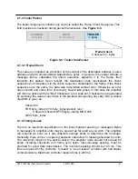
Page 53: ...quest ID 0 to 255 Command 0 1 Data Tag 6 Response Length n 11 m Data Length 11 to 11 m Header 4 Bytes Command Preamble 6 Bytes Request Frame B 11 to 11 n Bytes Trailer Checksum 1 Byte Request Frame A...

Page 54: ...Version Request ID Command Data Tag Data Address Data Length Data Table 6 4 Request Frame Structure Table 6 5 Response Frame Structure Byte Tag Description 1 0xAA Frame Sync 1 2 0x55 Frame Sync 2 3 De...

Page 55: ...A Auxiliary Fault Status Ignore Auxiliary Fault 255 Fault on Logic Low State 1 Fault on Logic High State 0 Startup in Low Z State 2 Startup in High Z State 3 13 1 SSPA Auxiliary Fault Handling Minor F...

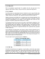
Page 56: ...2 RS485 1 3 IPNet 2 4 SNMP 3 10 1 Fiberlink interface 1 Off 0 2 On 1 11 12 2 Reserved 13 1 Fault Latch 1 Disable 0 2 Enable 1 14 15 2 Reserved 16 1 Menu Password Valid Values 0 255 17 1 Reserved 18 1...

Page 57: ...re Fault Bit 2 Auxiliary Fault Bit 3 Fiber RX Link Fault Bit 4 RF Switch Control 1 state Bit 5 RF Switch Control 2 state Bit 6 Reserved always 0 Bit 7 Unit On Line State 4 2 Present Attenuation Level...

Page 58: ...n N A 4 2 Current value of ADC channel 4 Gate Voltage Value Range 0 to 1023 Conversion 1 value 9 4mV 5 2 Current value of ADC channel 5 Regulator Voltage Value Range 0 to 1023 6 2 Current value of ADC...

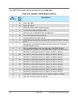
Page 59: ...t originating PC Host 5 0 Protocol Version Compatibility Field must always be 0 6 6F Request ID byte is set by originator will be echoed back by respondent 7 1 Command field for Get type request 8 0 S...

Page 60: ...gs requested from the SSPA 12 is all available data of System Conditions type 11 0 Data field 1 contains data element 1 of System Conditions data type 12 255 Data field 2 contains data element 2 of Sy...

Page 61: ...ag 0 indicates access to SSPA Settings 9 5 Data address 5 indicates access to SSPA attenuation 10 1 Data length is 1 byte 11 C8 Data 200 20 0 dB x 10 attenuation 12 4C Arithmetic checksum of bytes 3 t...

Page 62: ...equest 9 0x0C Data length indicates Packet Wrapper is 12 bytes long 10 0x0C Expected length of response packet from CO SSPA is 12 bytes long 11 0xAA Frame B Sync Byte 1 first byte of encapsulated fram...

Page 63: ...onse packet from CO SSPA is 12 bytes long 11 0xAA Frame B Sync Byte 1 first byte of encapsulated frame B 12 0x55 Frame B Sync Byte 2 13 0x64 Destination Address of the PC Host 14 0x01 Source address o...

Page 64: ...remote terminal must be also configured as an ASCII terminal at 9600 Baud no parity 8 bit data with 1 stop bit serial connection The RCPF 1000 will not echo back any incoming characters so local echo...

Page 65: ...and configured to use TMSP at 9600 Baud 1 Start the Windows HyperTerminal Program default Windows location at Programs Accessories HyperTerminal 2 At the prompted window type the name of your serial c...

Page 66: ...ed to turn on Local Echo on HyperTerminal itself To do so from the HyperTerminal top menu select as followed File Properties Settings ASCII setup The resulting window is shown on Figure 6 10 Check the...

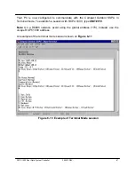
Page 67: ...the Compact Outdoor SSPA in Terminal mode To establish a session with RCP2 1000 type UNIT 170 Note On a RS485 network avoid using the global address 170 Instead use the unique RCPF 1000 address An exa...

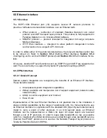
Page 68: ...and ARP are supported as well There is currently no support for dynamic IP parameters settings DHCP 6 5 2 IPNet Interface 6 5 2 1 General Concept Satcom system integrators are recognizing the benefit...

Page 69: ...r of ports that are not conflicting with standard IP services Paradise Datacom recommends usage of ports 1038 and 1039 These ports are not assigned to any known application As an application layer pro...

Page 70: ...r key select 6 Reset and press the Enter key To disable the Ethernet port and enable the RS232 485 port press the Main Menu key and select 2 PanelCom and press the Enter key then select 4 Interface an...

Page 71: ...y be set to another PC or network equipment with a different MAC address Open a Command Prompt window and type ARP a the press Enter The current table will be displayed If you see the RCPF 1000 IP add...

Page 72: ...The Java Applet uses a UDP socket to communicate with the SSPA If you are using a hardware or software firewall it will need notification that the Applet is authorized If the firewall is not notified...

Page 73: ...NMP Get SNMP GetNext and SNMP Set commands SNMP Traps are currently unsupported In order to utilize SNMP protocol the user has to enable this feature through the front panel or by remote serial protoc...

Page 74: ...x rwn Integer32 settingIndex 1 rwn Integer32 settingValue 2 r n OctetString settingTextValue 3 thresholds 2 thresholdsEntry 1 thresholdIndex rwn Integer32 thresholdIndex 1 r n Integer32 thresholdValue...

Page 75: ...ult 255 1 3 6 1 4 1 20712 2 1 1 1 2 13 SSPA Auxiliary Fault Handlin g 14 INTEGER BUCFaultCheck LogicHigh 0 LogicLow 1 Ignore 255 1 3 6 1 4 1 20712 2 1 1 1 2 14 Block Up Converter Fault Status 15 INTEG...

Page 76: ...1 1 2 37 Device Subnet Mask byte1 MSB 38 INTEGER IPSubnet Byte2 0 255 1 3 6 1 4 1 20712 2 1 1 1 2 38 Device Subnet Mask byte2 39 INTEGER IPSubnet Byte3 0 255 1 3 6 1 4 1 20712 2 1 1 1 2 39 Device Subn...

Page 77: ...3 6 1 4 1 20712 2 1 1 1 2 13 Fault Latch 14 INTEGER Reserved 0 255 1 3 6 1 4 1 20712 2 1 1 1 2 14 Field reserved for future use 15 INTEGER Reserved 0 255 1 3 6 1 4 1 20712 2 1 1 1 2 15 Field reserved...

Page 78: ...1 1 2 37 Device Subnet Mask byte1 MSB 38 INTEGER IPSubnet Byte2 0 255 1 3 6 1 4 1 20712 2 1 1 1 2 38 Device Subnet Mask byte2 39 INTEGER IPSubnet Byte3 0 255 1 3 6 1 4 1 20712 2 1 1 1 2 39 Device Subn...

Page 79: ...ate 6 INTEGER AuxiliaryFault NoFault 0 Fault 1 N A 2 1 3 6 1 4 1 20712 2 1 3 1 2 6 Auxiliary fault state 7 INTEGER BUCFault NoFault 0 Fault 1 N A 2 1 3 6 1 4 1 20712 2 1 3 1 2 7 BUC fault state 8 INTE...

Page 80: ...any other value will default type to cosspa OID 1 3 6 1 4 1 20712 1 4 devices This field is subdivided into 5 branches paradiseDevice paradiseDeviceA par adiseDeviceB paradiseDeviceC and modem paradi...

Page 81: ...the Enter key when complete 2 Set up the unit gateway address Select the following sequence from the unit Main Menu Main Menu 2 PanelCom 5 IP Setup 4 Gateway Then by using the navigation keys adjust...

Page 82: ...radise Datacom LLC MIB file into the Getif Mibs sub folder 2 Start the GetIf application 3 Select the unit IP address and community strings in the relevant text boxes on the Parameters tab see Figure...

Page 83: ...r is a software module that listens to the SNMP notifications sent by SNMP agents The manager can also send requests to an agent to collect remote information from the Management Information Base MIB...

Page 84: ...mbedded controllers and microprocessors that are used in electronic compo nents such as amplifier modules do not have support for SNMP V2 or V3 This is due to the extensive memory resources required b...

Page 85: ...carded as soon as it is sent an inform request must be held in memory until a response is received or the request times out Also a trap is sent only once while an inform may be retried several times T...

Page 86: ...86 209872 REV RCPF 1000 Fiber Optic System Controller THIS PAGE LEFT INTENTIONALLY BLANK...

Page 87: ...d dusted using an appropriate polishing material and a dust free source of compressed air Always apply caps and dust covers to all non terminated optical connectors Warning A single fingerprint or spe...

Page 88: ...the polarity of duplex cables with this type of connector Ultra Physical Contact UPC connectors are often used in digital CATV and telepho ny systems The end faces are given an extended polishing for...

Page 89: ...ty IFL between the indoor equipment and outdoor equipment The system designer must always consider the total cable loss for a given length and also the implications of the slope of attenuation across...

Page 90: ...s monitoring of the various internal conditions of the remote SSPA These include Base plate temperature Power supply output voltage SSPA DC Current consumption Regulator output voltage RF Output level...

Page 91: ...his fault is effective when the remote SSPA internal voltage regulators drop output voltage below 8 volts This fault always retains its last state when the SSPA is muted The fault threshold value is f...

Page 92: ...s an abnormally low current consumption This fault always retains its last state when the SSPA is muted The fault threshold value is fixed and cannot be changed by the user The Current Fault Alarm LED...

Page 93: ...available only for Compact Outdoor SSPAs with the internal 0dBm BUC option In general the BUC fault is a major fault The Summary Fault Alarm LED on the front panel will light Check the front panel LC...

Page 94: ...display No Connection Com Link Lost This condition will not prevent the user from browsing through the RCPF 1000 menus to observe the last read parameters of the remote unit The display will automatic...

Page 95: ...ownload from it s website at http www paradisedata com LNB fault is set as a major fault by the factory If a different level of fault handling is required please contact Teledyne Paradise Datacom LLC...

Page 96: ...n the RCPF 1000 and the OCM 1000 and between the OCM 1000 and the Compact Outdoor unit 7 4 14 Fiber Receive Line Faults An interruption of the RX signal in a fiber system will result in both a Fiber F...

Page 97: ...ify whether your unit uses the standard AC supply or the op tional 48V DC supply 7 5 1 3 RCPF 1000 Firmware The internal firmware is field programmable in the RCP redundant controller This section det...

Page 98: ...rn on the unit s power Step 5 After all connections have been made and all zip files unpacked locate the batch file within the _code subfolder which suits your LPT port designation For example prg_LPT...

Page 99: ...roller to a host PC through a crosso ver null modem network cable see Appendix B for wiring details 2 If the PC NIC card has not previously been set do so now using the following procedure otherwise s...

Page 100: ...0ms TTL 128 Reply from 192 168 0 3 bytes 32 time 10ms TTL 128 Reply from 192 168 0 3 bytes 32 time 10ms TTL 128 Ping statistics for 192 168 0 3 Packets Sent 4 Received 4 Lost 0 0 loss Approximate roun...

Page 101: ...8 0 0 bytes 32 time 10ms TTL 128 Reply from 192 168 0 0 bytes 32 time 10ms TTL 128 Reply from 192 168 0 0 bytes 32 time 10ms TTL 128 Ping statistics for 192 168 0 3 Packets Sent 4 Received 4 Lost 0 0...

Page 102: ...102 209872 REV RCPF 1000 Fiber Optic System Controller THIS PAGE LEFT INTENTIONALLY BLANK...

Page 103: ...ground and an orange stripe The straight through and crossover patch cables are terminated with CAT 5 RJ 45 modular plugs RJ 45 plugs are similar to those you ll see on the end of your telephone cable...

Page 104: ...netic fields are opposite and have a tendency to cancel the effect of each other This reduces the line s impact on the other pair of wires and the rest of the world The second and the primary means of...

Page 105: ...cable ends in the preceding diagrams they correspond to the 568A and 568B RJ 45 jacks and are shown in Figure B 6 Figure B 4 Ethernet Wire Color Code Standards Figure B 5 Wiring Using 568A Color Codes...

Page 106: ...ble will work in a 568A network Here are some essential cabling rules 1 Try to avoid running cables parallel to power cables 2 Do not bend cables to less than four times the diameter of the cable 3 If...

Page 107: ...ot required although it is recommended If a Unit ID isn t entered the Unit ID will be assigned by the M C To add a unit connected to a serial port you must supply a Port and a Baud Rate To add a unit...

Page 108: ...ects the current conditions or state of the Rack Mount SSPA In addition the status screen allows for Mute Unmute of the carrier and manual adjustment of the on board Attenuator for gain control The se...

Page 109: ...e new IP Address Until the SSPA is reset it will use the old IP Address The Amplifier Local Port is the port that the SSPA listens to for UDP requests The SSPA also answers requests using the same por...

Page 110: ...110 209872 REV RCPF 1000 Fiber Optic System Controller THIS PAGE LEFT INTENTIONALLY BLANK...

Page 111: ...screws should be threaded through the mounting holes in the OFM 1000 and into the four self adhering pems in the support plate Tighten the screws to 25 in lb 3 in lb Table D 1 OFM 1000 Mounting Kit Bi...

Page 112: ...asten with the 3 8 16 Hex Nut Item 04 and 3 8 Flat Item 02 and 3 8 Split Lock Item 03 washers See Figure D 3 Finger tighten only Loop the second U Bolt over the antenna boom and slide the 3 4 Round Sp...

Page 113: ...113 Appendix E Quick Start Guide Equipment needed Obtain the following equipment before proceeding with the set up and testing of the fiber system Spectrum Analyzer or Power Meter Crossguide coupler...

Page 114: ...he system uses WDMs therefore all fibers radiate optical power All optical connectors must be polished and dusted using an appropriate polishing material and a dust free source of compressed air Alway...

Page 115: ...xial cable Connect the spectrum analyzer or power meter to the system as shown in figure above Apply power to the system Using the front panel controls on the modem enable the TX 10MHz reference and C...

Page 116: ...e modem front panel Once the system has been verified to be operating according to specification a BER test can now be performed Reconnect the cable to the RCPF 1000 Port J22 RX IFL if necessary Switc...

Page 117: ...nsists of Specification Sheets 205485 Compact Outdoor SSPA 205489 Fiber Optic Interface for Compact Outdoor 209873 RCPF 1000 Remote Control Panel check our web site http www paradisedata com for the m...

Page 118: ...118 209872 REV RCPF 1000 Fiber Optic System Controller THIS PAGE LEFT INTENTIONALLY BLANK...

Reviews: