REMOTE CONTROL
151
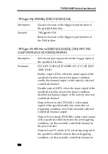
the load CV mode.
Output Load CC mode (CC): when input signal of
the specified cable line meets the set triggering
condition, set the currently controlled channel in
the load CC mode.
Output Load CR mode (CR): when input signal of
the specified cable line meets the set triggering
condition, set the currently controlled channel in
the load CR mode.
Output Individual mode (IND): when input signal of
the specified cable line meets the set triggering
condition, set CH1/CH2 in the individual power
mode.
Output Series mode (SER): when input signal of
the specified cable line meets the set triggering
condition, set CH1/CH2 in the series power
mode.
Output Parallel mode (PER): when input signal of
the specified cable line meets the set triggering
condition, set CH1/CH2 in the parallel power
mode.
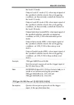
Example
:TRIGger:IN:RESPonse D0,ON
Sets the output response from the trigger input of
the D0 data line as ON.
Note
IND|SER|PAR takes CH1/CH2 as the main body, so it
needs to run before executing this parameter:
TRIGger:IN:SOURce Dx, CH1, ON and
TRIGger:IN:SOURce Dx, CH2, ON.
:TRIGger:IN:RESPonse? {D0|D1|D2|D3|D4}
Description
Queries the output response from the trigger
input of the specified data line
Summary of Contents for T3PS13206P
Page 1: ... ...
Page 106: ...T3PSX3200P Series User Manual 106 Register Commands OPC 187 OPC 187 ...
Page 177: ...REMOTE CONTROL 177 Example SAV 1 Recalls the setting stored in memory 2 STATE02 ...
Page 185: ...REMOTE CONTROL 185 Example STB Returns 81 if the status byte register is set to 0101 0001 ...
Page 196: ...T3PSX3200P Series User Manual 196 Between chassis and DC power cord 30MΩ or above DC 500V ...
Page 197: ... 0 0 0 1 2 3 4 5 6 7 8 8 9 3 3 3 45 6 990 0 0 9 0 0 0 9 0 0 0 0 9 7 7 88 8 1 931711 RevB ...

