BASIC OPERATION
59
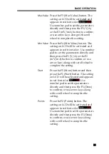
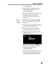
setting followed by pressing F1 (Done)
key to confirm; or use arrow keys along
with scroll wheel to complete setting.
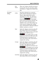
End State
Under the Delay function, press the F1
(Set) button followed by selecting the
F3 (Groups), and 2 statuses
Last/Output off will appear in turn on
LCD
. The one
displaying is what’s called the current
status.
Stop
Condition
Under the Delay function, press the F3
(Stop) button and halt the operation by
setting voltage F2 (Voltage), current F3
(Current) and power F4 (Power), or
Stop infinitely by F1 (None).
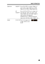
Operation
ON/OFF
Press the F5 (Delay On) button. Output
is open when output lights up; whilst
output is off when output lights out.
DLY appears on the status bar (yellow
for CH1, blue for CH2, and white for
both CH1 & CH2 on).
Warning
If the channel has been in Output ON before Delay
function, the status remains unchanged until
Delay.On so that the corresponding waveform starts
to output.
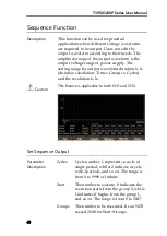
Set Group Parameter
Description
Each Group consists of Voltage, Current and
Time. Therefore, properly confirm parameter of
each group is correct before setting Delay output.
Parameter
Descriptiom
No.
Group number. Maximum 2047
State
Output status of each group: On, Off
Time
Execution duration of each group.
Summary of Contents for T3PS13206P
Page 1: ... ...
Page 106: ...T3PSX3200P Series User Manual 106 Register Commands OPC 187 OPC 187 ...
Page 177: ...REMOTE CONTROL 177 Example SAV 1 Recalls the setting stored in memory 2 STATE02 ...
Page 185: ...REMOTE CONTROL 185 Example STB Returns 81 if the status byte register is set to 0101 0001 ...
Page 196: ...T3PSX3200P Series User Manual 196 Between chassis and DC power cord 30MΩ or above DC 500V ...
Page 197: ... 0 0 0 1 2 3 4 5 6 7 8 8 9 3 3 3 45 6 990 0 0 9 0 0 0 9 0 0 0 0 9 7 7 88 8 1 931711 RevB ...

