TIENet™ 360 LaserFlow™ Velocity Sensor
Section 2 Preparation and Installation
2-17
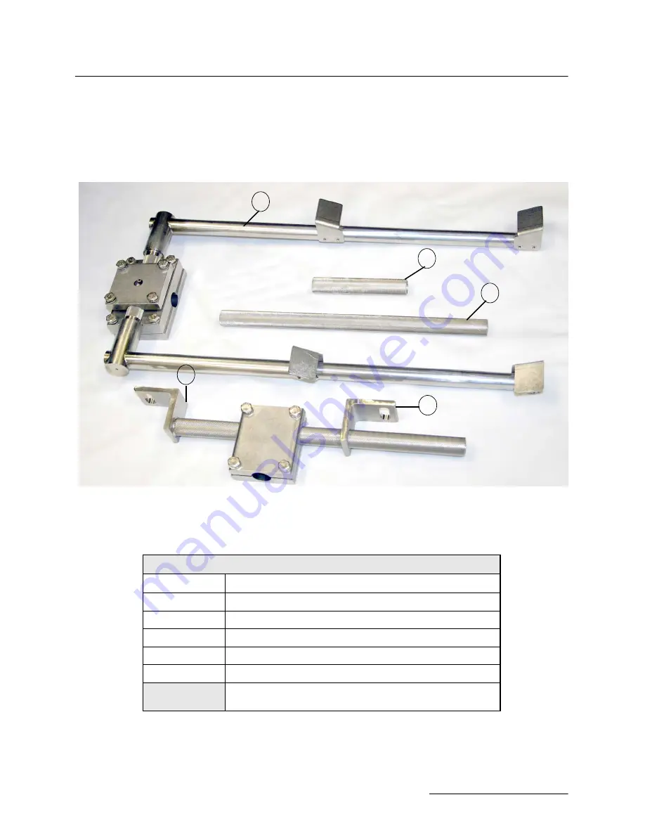
2.6 Wall Mounting Kit
For wall mounting, identify the components listed in Figure 2-18
and Table 2-1, and perform the steps that follow. Order numbers
for parts and fasteners are provided in Appendix A.
Figure 2-18 Wall mounting kit (Numbers correspond with
Table 2-1)
4
5
2
3
1
Table 2-1 Wall Mounting Kit
Item (Callout #)
Description
1
Tube Coupler (short)
2
Tube Coupler (long)
3
Bottom Wall Mount Angle Bracket (adjustable)
4
Mounting Shaft
5
Sensor Carrier
SST Anchor Stud Assembly & Spring Lock Washers
(for fastening brackets to wall)
Summary of Contents for TIENet 360 LaserFlow Ex
Page 2: ......
Page 4: ......
Page 10: ...TIENet 360 LaserFlow Velocity Sensor Safety viii ...
Page 54: ...TIENet 360 LaserFlow Velocity Sensor Section 2 Preparation and Installation 2 32 ...
Page 90: ...TIENet 360 LaserFlow Velocity Sensor Section 4 Setup with 2160 LaserFlow Module 4 20 ...
Page 102: ...TIENet 360 LaserFlow Velocity Sensor Appendix A Replacement Parts A 2 A 2 LaserFlow Sensor ...
Page 103: ...TIENet 360 LaserFlow Velocity Sensor Appendix A Replacement Parts A 3 ...
Page 104: ...TIENet 360 LaserFlow Velocity Sensor Appendix A Replacement Parts A 4 ...
Page 105: ...TIENet 360 LaserFlow Velocity Sensor Appendix A Replacement Parts A 5 ...
Page 106: ...TIENet 360 LaserFlow Velocity Sensor Appendix A Replacement Parts A 6 ...
Page 107: ...TIENet 360 LaserFlow Velocity Sensor Appendix A Replacement Parts A 7 ...
Page 109: ...TIENet 360 LaserFlow Velocity Sensor Appendix A Replacement Parts A 9 ...
Page 111: ...TIENet 360 LaserFlow Velocity Sensor Appendix A Replacement Parts A 11 ...
Page 132: ...TIENet 360 LaserFlow Velocity Sensor D 6 ...
Page 136: ......
Page 138: ...Warranty ...
Page 140: ......


