TIENet™ 360 LaserFlow™ Velocity Sensor
Section 3 Setup with Signature® Flow Meter
3-5
3.2.1 360 Level
The
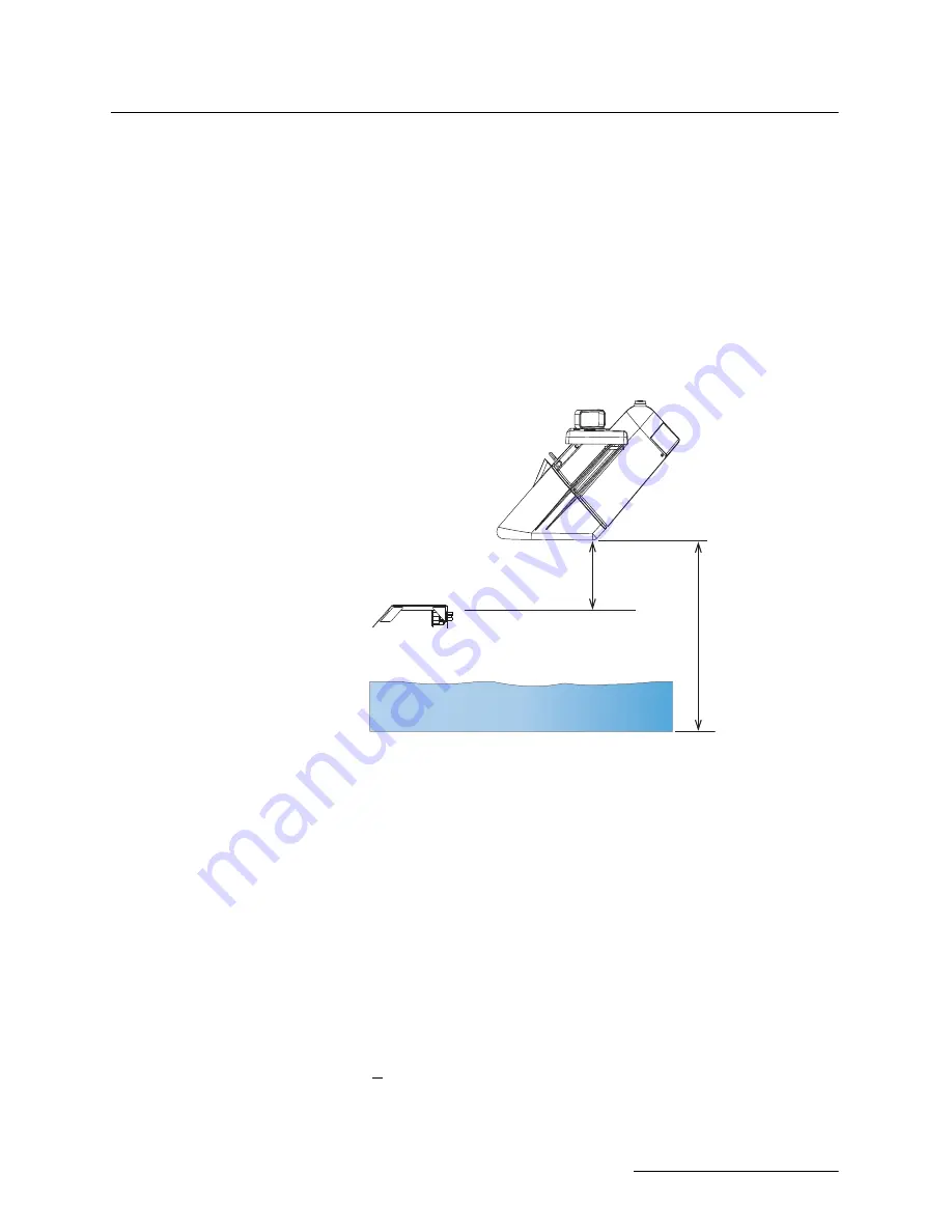
Minimum Blanking Distance
is the distance from the
bottom of the sensor to the liquid surface at the highest expected
level. Depending on the elevation of your sensor, this value may
be increased to help ensure that echoes read by the flow meter
come only from the surface of the flow stream, and not off the
walls or sides of the channel.
The
Maximum Blanking Distance
is the distance between the
bottom of the sensor and the bottom of the channel (i.e., zero
level). A larger value than calculated can be entered.
If using the LaserFlow module with the 310 remote ultrasonic
sensor and horizontal sensor mounting bracket, the maximum
blanking distance is the distance between the bottom of the
mounting bracket and the bottom of the channel.
Figure 3-4 Blanking distance for LaserFlow with built-in sensor or with remote
ultrasonic sensor
3.2.2 360 Velocity
When the
Measure
Positive Velocity only
option is selected,
the LaserFlow will not attempt to determine flow direction and
negative readings are discarded in the average velocity calcu-
lation. Selecting this setting will save power. By default, this
options is selected.
When the Positive Velocity option is deselected, a second velocity
measurement is taken to determine the direction of the flow.
3.2.3 LaserFlow Velocity
Advanced Settings
The LaserFlow
Advanced Settings
are pre-programmed into
the sensor. However, if your application requires any custom con-
figuration, the Advanced button opens the Advanced settings
window (refer to Figure 3-5).
Input Velocity Coefficients –
The relationship of the three
Input Velocity Coefficients A, B and C can be expressed as:
V = A (offset) + B*(Measured Velocity) + C*(Measured Velocity)
2
Bottom of Channel
Maximum Expected Level
Minimum Blanking
Maximum Blanking
Summary of Contents for TIENet 360 LaserFlow Ex
Page 2: ......
Page 4: ......
Page 10: ...TIENet 360 LaserFlow Velocity Sensor Safety viii ...
Page 54: ...TIENet 360 LaserFlow Velocity Sensor Section 2 Preparation and Installation 2 32 ...
Page 90: ...TIENet 360 LaserFlow Velocity Sensor Section 4 Setup with 2160 LaserFlow Module 4 20 ...
Page 102: ...TIENet 360 LaserFlow Velocity Sensor Appendix A Replacement Parts A 2 A 2 LaserFlow Sensor ...
Page 103: ...TIENet 360 LaserFlow Velocity Sensor Appendix A Replacement Parts A 3 ...
Page 104: ...TIENet 360 LaserFlow Velocity Sensor Appendix A Replacement Parts A 4 ...
Page 105: ...TIENet 360 LaserFlow Velocity Sensor Appendix A Replacement Parts A 5 ...
Page 106: ...TIENet 360 LaserFlow Velocity Sensor Appendix A Replacement Parts A 6 ...
Page 107: ...TIENet 360 LaserFlow Velocity Sensor Appendix A Replacement Parts A 7 ...
Page 109: ...TIENet 360 LaserFlow Velocity Sensor Appendix A Replacement Parts A 9 ...
Page 111: ...TIENet 360 LaserFlow Velocity Sensor Appendix A Replacement Parts A 11 ...
Page 132: ...TIENet 360 LaserFlow Velocity Sensor D 6 ...
Page 136: ......
Page 138: ...Warranty ...
Page 140: ......


