TIENet™ 360 LaserFlow™ Velocity Sensor
Section 4 Setup with 2160 LaserFlow Module
4-18
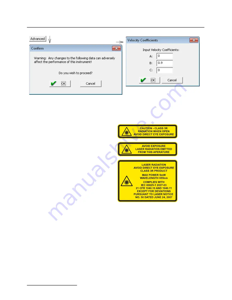
Figure 4-16 350 Velocity tab: Advanced settings for optional TIENet 350 AV sensor
4.3 Sensor Positioning
and Adjustment
To set the initial level values, refer to Sections 4.2.1 (LaserFlow)
and 4.2.4 (optional 350).
4.3.1 Centering the
LaserFlow Sensor
Proper positioning of the LaserFlow sensor is critical for optimal
velocity measurement. In center position, the laser beam must
strike the flow stream precisely in the center.
The beam automatically moves to the top center position.
Laser on
Select the “
Laser on
” button and click the “
Apply
” button. This
will keep the laser beam on continuously for 10 minutes or until
the “
Laser off
” button is clicked, allowing the beam to be used
for fine-tuning the sensor’s position.
Summary of Contents for TIENet 360 LaserFlow Ex
Page 2: ......
Page 4: ......
Page 10: ...TIENet 360 LaserFlow Velocity Sensor Safety viii ...
Page 54: ...TIENet 360 LaserFlow Velocity Sensor Section 2 Preparation and Installation 2 32 ...
Page 90: ...TIENet 360 LaserFlow Velocity Sensor Section 4 Setup with 2160 LaserFlow Module 4 20 ...
Page 102: ...TIENet 360 LaserFlow Velocity Sensor Appendix A Replacement Parts A 2 A 2 LaserFlow Sensor ...
Page 103: ...TIENet 360 LaserFlow Velocity Sensor Appendix A Replacement Parts A 3 ...
Page 104: ...TIENet 360 LaserFlow Velocity Sensor Appendix A Replacement Parts A 4 ...
Page 105: ...TIENet 360 LaserFlow Velocity Sensor Appendix A Replacement Parts A 5 ...
Page 106: ...TIENet 360 LaserFlow Velocity Sensor Appendix A Replacement Parts A 6 ...
Page 107: ...TIENet 360 LaserFlow Velocity Sensor Appendix A Replacement Parts A 7 ...
Page 109: ...TIENet 360 LaserFlow Velocity Sensor Appendix A Replacement Parts A 9 ...
Page 111: ...TIENet 360 LaserFlow Velocity Sensor Appendix A Replacement Parts A 11 ...
Page 132: ...TIENet 360 LaserFlow Velocity Sensor D 6 ...
Page 136: ......
Page 138: ...Warranty ...
Page 140: ......


