background image


Installation 


Vision G2 Testers User Guide—74-108-800 Rev. H—12 June 2019 

41 of 158 

Liquid Line Connections 

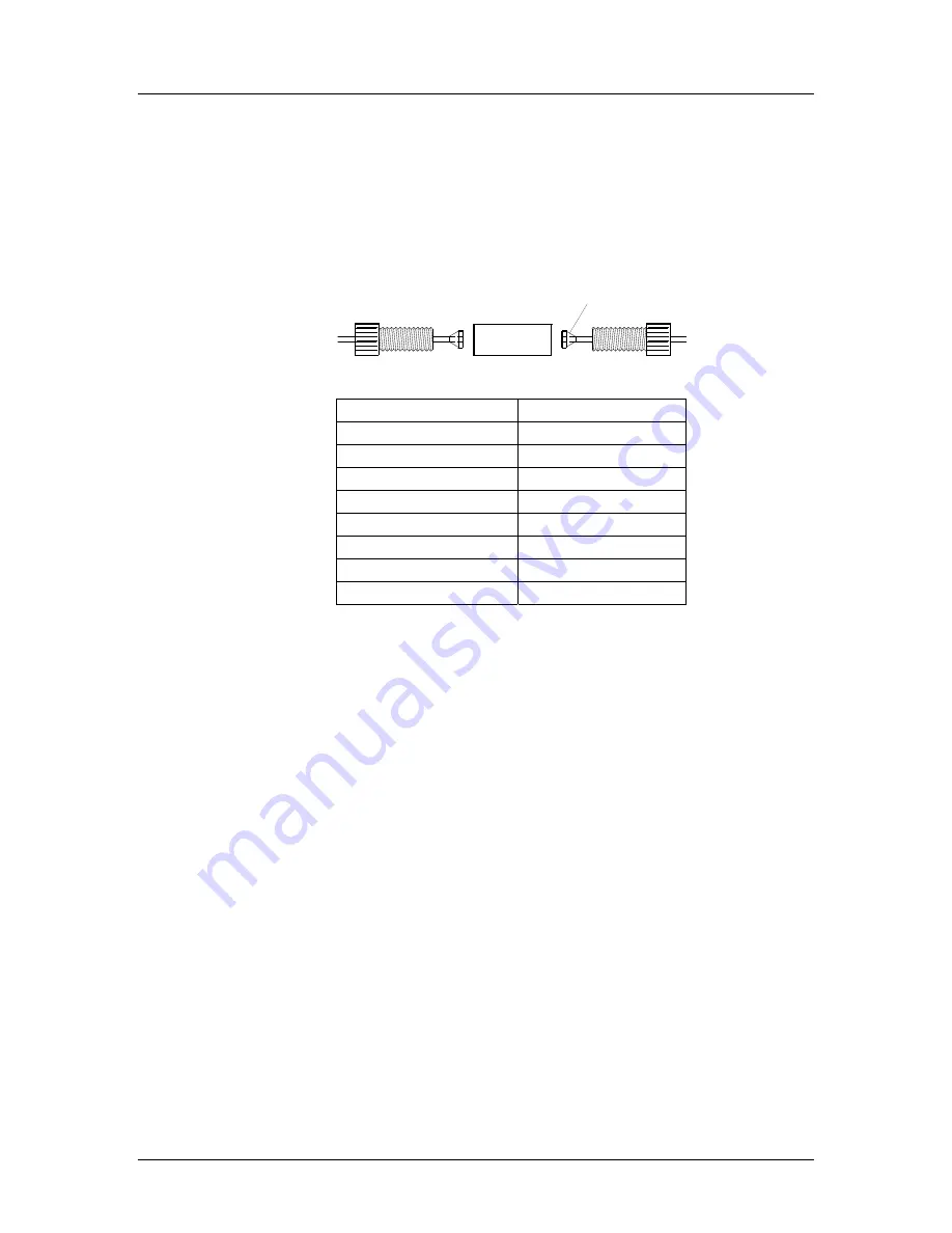
Sample  line  connections  are  made  by  connecting  the  six  or 
eight  liquid  tubes  from  the  Vision  AutoPlus/AutoFill  or  other 
autosampler to the dissolution tester. These are numbered and 
color-coded for easy identification. They can be connected with 
nuts, unions, and ferrules as shown in the figure below: 


Position 

Fitting Color 

Black 

Red 

White 

Yellow 

Green 

Blue 

Clear 

Purple 


Fig. C-12 Liquid Line Connections 

Security 

The Vision tester can be configured to require users to log in 
and  allows  for  tracking of  any  changes  made  to  the  protocol. 
The security system allows for 25 users when using firmware 
versions below 2.50 and 50 users for versions 2.50 and above. 

Firmware  versions  below  2.70  offer  two  levels  of  users 
(managers and operators) with fixed permissions: 

  Managers are given full access to the unit and allowed to 

make any changes to the system as required, with all 
these changes being tracked by the software. All users 
can be configured as managers for full control of the 
Vision tester. One manager is required by the software. 
Hanson is installed as a manager from the factory. The 
default password for the Hanson manager is 0000. 

  Operators are permitted to run tests but are not allowed to 

make changes to protocols or other system settings. Not 
all users can be configured as operators; the software 
requires at least one user be configured as a manager. 

UNION

NUT

FERRULE

Summary of Contents for VISION G2 CLASSIC 6

Page 1: ...VISION G2 CLASSIC 6 AND ELITE 8 DISSOLUTION TESTERS USER GUIDE 74 108 800 Rev H 12 June 2019...

Page 2: ...ology Teledyne Hanson Research THR helps ensure the world s pharmaceuticals are pure safe and effective by manufacturing equipment that sets the global standard for quality innovation and long term va...

Page 3: ...uct we also understand from time to time you may have a question or technical issue requiring our assistance Please feel free to contact us at any time by any of the methods below Website teledynehans...

Page 4: ...etwork configurations Added Appendix C on Waters Transfer Module Improved information on archiving and checksums for protocols D 01 Jul 2013 Added leveling procedure to installation Added ADD cover fo...

Page 5: ...UIDELINES FOR CLEANING THE WATERBATH 35 VERIFICATION OF MANUAL CONTROLS 36 VISION TESTER COMMUNICATION CONNECTIONS 36 LIQUID LINE CONNECTIONS 41 SECURITY 41 DRIVE HEAD MOVEMENT ELITE 8 ONLY 46 PADDLE...

Page 6: ...LF TEST 129 NETWORK PRINTER TROUBLESHOOTING 130 SPECIFICATIONS 131 VISION G2 CLASSIC 6 SPECIFICATIONS 131 VISION G2 ELITE 8 SPECIFICATIONS 131 VISION G2 HEATER SPECIFICATIONS 132 VISION G2 DISSOLUTION...

Page 7: ...BATH TO HEATER TUBING CONNECTION 30 FIG C 7 ELITE 8 BATH TO HEATER TUBING CONNECTION 30 FIG C 8 FILL WATERBATH TO APPROPRIATE LINE ON STICKER 31 FIG C 9 INSERT THE TUBING FROM THE SYRINGE INTO THE FI...

Page 8: ...dissolution test operator requirement is evaluated and simplified for ease of use and fast results Our test systems are designed for the dissolution laboratory with a tight schedule and a heavy worklo...

Page 9: ...with 4 way solenoid valves per syringe to direct fluid flow The Maximizer provides 4 fluid lines A B C and D Up to 3 testers or 2 testers with media replace can be connected to a Maximizer Occurrence...

Page 10: ...Easi Lock vessels securely in place Vision AutoFilter A programmable filter changing instrument which uses 25 mm in line syringe filters Vision AutoPlus The redesigned Teledyne Hanson autosampler ser...

Page 11: ...with optional AutoMag SuperMag Precision control for speed 25 250 rpm temperature 25 55 C Elegant ergonomic design with workhorse performance Highest quality components and engineering Minimal user ad...

Page 12: ...ion G2 Testers User Guide 74 108 800 Rev H 12 June 2019 11 of 158 Vision G2 Tester Identification Figure A 1 Identification Vision G2 Classic 6 Tester Shaft clamp Touchscreen Spindle shaft Power switc...

Page 13: ...Vision G2 Testers User Guide 74 108 800 Rev H 12 June 2019 12 of 158 Figure A 2 Identification Vision G2 Elite 8 Tester Shaft clamp Power switch AutoMag Vision heater Touchscreen Drive head handle Sp...

Page 14: ...Buttons In order to use a button touch it with your finger or a stylus Buttons may appear as having text or as icons Sliders In order to use a slider place a finger on the slider button and slide the...

Page 15: ...specific formats which must be observed when entering information These limits and formats are stated in the upper left corner of the screen below the field name For example the IP address of the Visi...

Page 16: ...uttons are located on the left side of the screen and allow access to different parts of a section of the software For example the Edit Alarms screen has 4 tabs that allow the editing of the Preheat A...

Page 17: ...to a USB flash drive This is a common button on many of the screens of the Vision tester NOTE For ease of reading it is recommended to open logs in a word processor Text editors e g Windows Notepad ma...

Page 18: ...isted as 0 0000 The motor speed and temperature are displayed on the left side of the screen To adjust the motor speed touch the RPM SETPOINT field and a numeric keypad will appear Enter the desired m...

Page 19: ...external temperature probe Probe Error will be displayed Enter the desired temperature and touch Ok The pump will start and the temperature should begin to rise There are preset buttons for 32 C and...

Page 20: ...of raising or lowering the probes using the Raise or Lower arrows if AutoMag or SuperMag is installed and or printing the vessel temperatures using the Print button If there is an error with one of th...

Page 21: ...ol is already loaded the protocol name will appear in the upper left corner of the screen and when touched it will be opened for editing If no protocol is loaded Select Protocol will appear in the cor...

Page 22: ...s are enabled Please Log In appears in the corner If security features are not enabled a user can log on by touching the same corner of the screen Security Off appears in the corner of the screen and...

Page 23: ...is power to the unit Disconnect power before servicing the instrument Review all safety and environmental precautions pertaining to any chemicals that are to be used in conjunction with this equipmen...

Page 24: ...f Communications Le pr sent appareil num rique n met pas de bruits radio lectriques d passant les limites applicables aux appareils num riques de la classe A prescrites dans les r glements sur le brou...

Page 25: ...cluding water of each machine as laid out in the specifications section The first Vision G2 dissolution instrument should be placed to the left of an autosampler if used Additional testers should go t...

Page 26: ...Vision tester from the shipping container a Note any damage to the shipping container If container is damaged contact Teledyne Hanson Research immediately b Place shipping container near installation...

Page 27: ...he drive head is fixed and not adjustable Fig C 1 Remove Locking Bolts h Once the locking bolts are removed the Elite 8 drive head can be moved by pulling the lock release lever on the left underside...

Page 28: ...4 feet as necessary ii For the Elite 8 adjust the 2 front feet and the foot located underneath the mast When the tester is level adjust the 2 back feet for added support Place a vessel in each of the...

Page 29: ...tions to the Vision tester 1 Ensure the power switch located on the right side of the Vision tester is in the off O position 2 Connect the power supply to the port labeled Input on the back panel of t...

Page 30: ...ar side of the tester 2 Connect the tubing as shown in figure C 6 or C 7 3 Ensure hose clamps are on straight Tighten the clamps 3 to 5 clicks to prevent leaks NOTE A pair of pliers is required for pr...

Page 31: ...Installation Vision G2 Testers User Guide 74 108 800 Rev H 12 June 2019 30 of 158 Fig C 6 Classic 6 Bath to Heater Tubing Connection Fig C 7 Elite 8 Bath to Heater Tubing Connection...

Page 32: ...in damage to the Vision heater 1 Fill the waterbath to the line on the sticker located at the center front of the bath Fig C 8 Fill waterbath to appropriate line on sticker Go to the Temperature Setp...

Page 33: ...itting on the side of the bath to ensure bubbles are being pushed out If no bubbles are pushed out push the tubing down farther into the fitting Repeat steps 2 through 4 until only water is pushed out...

Page 34: ...o may result in damage to the Vision heater Wait for consistent flow from the drain hose When the pump has been primed the noise from the Vision heater should decrease Disconnect the drain hose and re...

Page 35: ...temperature during this process Doing so may result in damage to the Vision heater 1 Remove a vessel over the bath output fitting 2 Insert the drain plug into the bath output fitting This will allow t...

Page 36: ...aterbaths of the Classic 6 and Elite 8 1 Use only a soft cloth when wiping down the waterbath Coarse materials may scratch the bath material 2 Use only warm water when cleaning the bath or at any othe...

Page 37: ...emperature set point screen should appear 6 Touch the 37 button to set the bath temperature to 37 C 7 Observe the temperature on the home screen and ensure that the temperature begins to rise Vision T...

Page 38: ...on Vision G2 Testers User Guide 74 108 800 Rev H 12 June 2019 37 of 158 3 From the home screen touch the Menu button to bring up the tester menu screen 4 Touch the Time button to bring up the Edit Ala...

Page 39: ...n 6 The Edit Time Date screen will appear Touch the System Date field to set the current date Enter the date in the DD MM YYYY format and touch OK when done 7 The Edit Time Date screen will reappear T...

Page 40: ...u 9 Touch the Config button to bring up the system configuration screens 10 The first tab is Instrument Touch the Instrument ID field to edit the instrument ID for the tester This ID will appear on pr...

Page 41: ...192 168 1 20 then the IP address of the printer must begin with 192 168 1 For more information on configuring IP addresses refer to appendix B 12 Touch the Gateway Address field to edit the gateway a...

Page 42: ...protocol The security system allows for 25 users when using firmware versions below 2 50 and 50 users for versions 2 50 and above Firmware versions below 2 70 offer two levels of users managers and op...

Page 43: ...enu and the Security Configuration screen will appear Status Enables or disables the security feature Inactivity Timeout The amount of time without user input before the system requires a user to log...

Page 44: ...he diagnostics routine on the instrument Display Settings Allows the ability to adjust the display brightness volume and recalibrate the screen Edit Protocols Allows the ability to edit and create pro...

Page 45: ...time date Instrument ID and network configuration settings Only users with permission to edit security settings can display the User List The users are listed alphabetically and displayed in groups o...

Page 46: ...Backup Allows a manager to create and send a backup of the instrument s security configuration including the users and corresponding profiles to a flash drive in the USB port The security configuratio...

Page 47: ...indle shaft is factory adjusted to provide the correct height for baskets and paddles The precision design of the Easi Lock vessels the shaft components and the test unit itself are intended to reduce...

Page 48: ...tion ensure that the key of the shaft clamp and the key on the spindle itself are at the same level so that they will lock together Fig C 13 Shaft Clamp and Key in Position Vessel Cover Installation E...

Page 49: ...t to slide through If an AutoMag is installed align the cover with the sample probes NOTE This ADD cover is compatible with the AutoMag but NOT the SuperMag 2 Slide the cover so that the spindle shaft...

Page 50: ...ndle shaft is in the center of the cover If an AutoMag or SuperMag is installed align the cover with the sample probes NOTE This ADD cover is compatible with SuperMag or AutoMag 2 Raise the cover and...

Page 51: ...lite 8 and shafts in place 1 Open the cover and slide it around the shaft so that the spindle shaft is in the center of the cover If an AutoMag is installed align the cover with the sample probes NOTE...

Page 52: ...to run diagnostics If OK is touched the diagnostics will run If Cancel is touched the diagnostics will not run and the operator will be returned to the menu This procedure performs a self test to che...

Page 53: ...g the About button located at the bottom of the info screen Tester Firmware Version number of the tester firmware Auxiliary CPU Firmware Version number of the auxiliary CPU firmware Bootloader Firmwar...

Page 54: ...to settings or editing of protocols The log will store the last 543 events Test Log This log lists all the actions that occurred during the last test It is overwritten when a new test is started NOTE...

Page 55: ...his is read by the software directly from the probe and cannot be changed Printer This is the serial number of the printer connected to the Vision tester this is generally reserved for serial validati...

Page 56: ...og screen The Service Log screen is accessed by the Service button at the bottom of the screen To update the service logs touch the appropriate field for the item to be updated and the current date wi...

Page 57: ...moved up and down and the date since the motor was last replaced Display The Display button allows the user to access the Touchscreen Settings screen Brightness This screen allows the user to adjust t...

Page 58: ...n back to the factory default settings for brightness and volume Configuration Touch the Config button on the menu to bring up the Device Setup screen Device Setup screen The Device Setup screens allo...

Page 59: ...b The Printer tab allows the user to configure the printer the Vision tester will use Printer Type When touched toggles the type of printer connected to the instrument Network Used when the printer is...

Page 60: ...work printers which do not support color printing will print normally in black and white even if this is set to Yes Yes or No Accessories tab The Accessories tab allows the user to define the accessor...

Page 61: ...onfiguration is accessed by touching the Titles button at the bottom of the Device Setup screen The titles configuration screen allows the user to set the desired titles for the test headers protocols...

Page 62: ...Load a Custom Logo 1 Prepare a jpeg image that meets the following requirements a No more than 100 pixels wide by 50 pixels high b 96 dpi c File size 15 KB or less d Named logo jpg 2 Load the image in...

Page 63: ...if security is enabled the name of the user logged in is automatically displayed This label cannot be changed Test Name A test name if applicable Lot Number The lot number of the item being tested Co...

Page 64: ...ution test i e 900 mL Apparatus tab The Apparatus tab allows for editing the field of the apparatus labels section Up to 8 label fields are available each having a maximum length of 25 characters The...

Page 65: ...he firmware update feature uploads the file timage hru from the root of the USB flash drive The firmware update process is automated and takes up to 5 minutes to complete Protocols system settings sec...

Page 66: ...reheat Alarm screen This screen allows the user to enable a preheat wakeup alarm The waterbath heats to the set point at the specified time and date This allows the tester to be ready for the start of...

Page 67: ...n Fri The alarm will occur every Monday through Friday Mon Sat The alarm will occur every Monday through Saturday Sampling Alarm tab This screen provides the user with the ability to enable a sampling...

Page 68: ...te the alarm will begin or Disabled Recurrence Toggles between the following values Disabled The alarm will occur only once at the time and date set and will not recur Every day The alarm occurs every...

Page 69: ...reen Alarm Time The time the alarm will begin Alarm Date The date the alarm will begin or Disabled Recurrence Toggles between the following values Disabled The alarm will occur only once at the time a...

Page 70: ...the current month Jan Dec and YYYY is the year in the long format 2009 2999 The entry of the format is numerical having the format DD MM YYYY The System Time format is 24 hour time military time as HH...

Page 71: ...provides access to basic control for movement of the magazine Magazine Calibration screen The Magazine Calibration screen is also accessed by touching the Cal Mag button at the bottom of the screen Ma...

Page 72: ...factory However if it needs to be recalibrated use the following procedure from the Magazine Calibration screen 1 Place the AutoMag calibration tool in the center of the vessel plate See Fig D 1 for p...

Page 73: ...ch the Calibrate button This will bring up a pop up screen that asks if the calibration tool is in place Select OK to confirm 3 The AutoMag or SuperMag will lower then stall on the calibration tool th...

Page 74: ...nd Vessel Probes To adjust the offset of a probe touch the field in which it is listed and a numeric keypad will appear Enter the correct temperature as measured by an NIST traceable thermometer to ma...

Page 75: ...Instrument Temperatures screen Log Instrument Temperatures screen is accessed by touching the Log Temp button at the bottom of the screen This screen allows users with only an external temperature pr...

Page 76: ...will replace the buttons at the bottom of the screen A Log button will appear on the pop up when starting or ending a test This allows the user to log temperatures before during and after a test and...

Page 77: ...name displayed in the upper left corner of the home screen Protocols are a list of parameters and events that are required to perform a dissolution test These parameters can be modified to accommodate...

Page 78: ...otocols is identical to the original set When touched the Protocols check pop up is displayed which first informs the user the value is being calculated then displays the calculated value For example...

Page 79: ...le named dproto bak NOTE Exporting the test log will overwrite any existing test log on the USB drive Restore This button allows protocols to be restored from the flash drive inserted into the USB por...

Page 80: ...f the user confirms an overwrite otherwise the existing protocol will remain Term 2 14 file name 2 20 file name Used for Existing protocols users Data sent Backup proto bak dproto bak All protocols or...

Page 81: ...th the tabs along the bottom of the screen Event Library Touching this will convert the protocol into an event library which is used with the Call event For more information see appendix E Export Expo...

Page 82: ...tester Comments Allows the user to add any notes specific to the protocol The following field names can also be edited by the user though the configuration settings on the title screen Drug Name The...

Page 83: ...e is 0 5 C Range is 0 off 0 10 to 5 00 C Test Length the total time of the dissolution test The range is 0 999 00 hh mm Digital Temp Probes Allows vessel temperature probes mounted on the AutoMag or S...

Page 84: ...s collects a sample Manual For manual sampling When manual sampling is selected the user has the option of defining how long the paddles remain spinning after a test has ended to allow for collection...

Page 85: ...han 15 mL for 12 x 32 vials no more than 1 5 mL This function only applies to Collect Only and Collect and Detect modes Media Replace Volume from the media replace source typically Source C if configu...

Page 86: ...would be a preset value for the proper magazine travel in a test involving 500 mL of media in each vessel The travel values are approximate and fine tuning may be necessary The suggested travel values...

Page 87: ...ed Disabled The protocol will not automatically start once the conditions are reached and it must be started manually Prompt When the protocol is set up to run the user will be prompted if they want t...

Page 88: ...is value to 0 00 The range is 0 00 to 9 59 in h mm format NOTE The infinity test begins after the dissolution test is over For example if a dissolution test was 2 hours with a 30 minute infinity test...

Page 89: ...Pre run and post run events cannot be sampling events Pre Run Events programmed as a pre run event will occur before the test begins For example an operator programs a pre run event of Drive Speed for...

Page 90: ...t table Start Time This defines the start of the first event The range is 0 00 to 999 00 hh mm Preset buttons are Pre Run and Post Run NOTE A warning will appear if sample points may overlap due to th...

Page 91: ...elected together with the Reuse Filter option for the same sample point Reuse Filter Instructs the AutoFilter to reuse the filter for the specified tester s Cannot be selected with Change Filter optio...

Page 92: ...s the user to set a new Detect Volume for the test S Dilute The options are dilution Volume Rinse volume Source StartRow and RowCount It allows the user to perform a dilution at the time of the event...

Page 93: ...rial The range is 0 6 to 23 8 mL min The default setting is 19 0 mL min NOTE 19 0 mL min should not be exceeded or the Vision G2 AutoPlus could be damaged B Mag Home Offset Version 2 64 and above only...

Page 94: ...ates a pop up message box with a message The message may be up to 11 characters in length S Read Delay This changes the read delay when working with collect and detect protocols The parameter is time...

Page 95: ...r to transfer a specified volume of solution from a specified source to a specified destination For example if a transfer of 5 mL from source C to source A is desired the parameter would read 5 C A Th...

Page 96: ...arameter is the time in seconds The default value for this is 7 seconds A minimum of 5 seconds is recommended B Vessel Goal Temperature The parameter is the temperature value It allows the user to cha...

Page 97: ...58 How to Program a Protocol Below are the instructions on how to program a basic protocol 1 Touch the Menu button on the home screen to bring up the menu 2 Touch the Protocols button on the menu to b...

Page 98: ...ol name touch the Protocol Name field and enter an appropriate protocol name NOTE Do not use a comma in the Protocol Name field Doing so will cause communication issues with the dissolution tester 5 T...

Page 99: ...to enter the appropriate information When finished touch the Sampling tab 8 Touch the Sampling Mode field to set the appropriate sampling mode 9 With the correct sampling mode entered proceed to enter...

Page 100: ...new event 12 Select the Start Time of the first event then the Event Type by touching the respective fields If there is more than one of the event as with sampling touch the number of events field to...

Page 101: ...14 If an event is not desired for example an extra sample point touch the field the event appears in 15 On the Edit Event screen touch the Delete button to remove the event 16 If no changes are neede...

Page 102: ...t The Prev button allows the user to return to the previous screen Header Information screen The header information screen allows the user to enter information specific to that test run The labels for...

Page 103: ...est report It includes the summary page and test log for the dissolution tester Heater Off At End Of Test This option causes the Vision tester to turn off the heater at the end of the dissolution test...

Page 104: ...e before the programmed time the test will start at the programmed time Start Date The date the test is scheduled to begin Start Time The time the test is scheduled to begin How to Use the Quick Start...

Page 105: ...ime field and set a test length if desired If no test length is set the test will run until the user touches the Stop button in the lower right corner of the home screen NOTE If Quick Start is not sel...

Page 106: ...start the test touch Run b To abort the test touch Abort c To log temperatures prior to dropping a tablet touch Log 6 When Run is touched the spindles will begin to turn at the set point The test wil...

Page 107: ...To start a test first begin at the home screen and touch protocol name or Select Protocol text in the upper left hand corner of the screen 2 Review the loaded protocol and touch the Exit button if ok...

Page 108: ...ome screen 4 Enter the appropriate information in the Header screen This is for information only and will appear on printed reports When finished press the Next button at the bottom of the screen 5 Se...

Page 109: ...r Guide 74 108 800 Rev H 12 June 2019 108 of 158 6 The Vision tester will return to the home screen If Auto Start is not enabled the tester will prompt the user to drop the dosage and press the Run bu...

Page 110: ...nd touch OK 4 Raise the apparatus out of the vessels by pulling up on the spindle shafts or in the case of a Vision Elite 8 raising the drive head 5 Fill the vessels with media 6 Prepare the apparatus...

Page 111: ...for testing 8 Touch the Start button in the lower right corner of the screen Enter the header information as appropriate then touch Next 9 Prepare the apparatus a Baskets i Place the dosage in each o...

Page 112: ...t iii Replace the vessel cover over position 1 iv Repeat the previous steps for each of the remaining positions in turn based on the desired stagger time c Paddles with ADD cover i Place the dosage in...

Page 113: ...K 4 Raise the apparatus out of the vessels by pulling up on the spindle shafts to their highest point or in the case of a Vision Elite 8 raising the drive head to its highest point 5 Fill the vessels...

Page 114: ...er information as appropriate then touch Next 9 Prepare the apparatus a Baskets Classic 6 i Place the dosage in each basket and install the baskets on the basket shafts ii Remove the vessel cover over...

Page 115: ...ch position iii Touch Run to start the test iv Replace the vessel covers over each position d Paddles with ADD cover i Place the dosage in each of the dose tubes located on the ADD cover for all posit...

Page 116: ...ture 0 10 C of the desired vessel temperature is recommended and touch OK 4 Raise the apparatus out of the vessels by raising the drive head 5 Fill the vessels with media 6 Prepare the apparatus a Bas...

Page 117: ...appropriate then touch Next Prepare the apparatus as instructed below Once the test is running the AutoMag will lower and begin monitoring the vessel temperatures if configured to do so a Baskets Elit...

Page 118: ...c Paddles with ADD cover i Place the dosage in each of the dose tubes located on the ADD cover for all positions ii Place the dose caps on top of the dose tubes for all positions iii Drop the dosage i...

Page 119: ...el Lower drive head if using an Elite 8 4 Place covers on vessel 5 Once the media has stabilized ensure the protocol is loaded by checking the upper left corner of the screen If the correct protocol i...

Page 120: ...wer drive head if using an Elite 8 4 Place covers on vessel 5 Once the media has stabilized ensure the protocol is loaded by checking the upper left corner of the screen If the correct protocol is loa...

Page 121: ...vessels with DI or better quality water Avoid harsh detergents which may damage the materials Weekly Inspect bath water for algae or other contaminants Drain and replace if necessary Monthly Replace b...

Page 122: ...ing the small dowel pin With the o ring pushed out slightly toward the center of the spindle it can be hooked using the tool 6 When replacing the o rings use the tool to guide each o ring into place t...

Page 123: ...he spindles and monument and then pressing down until it pops back into place 9 Reinstall the spindle shafts Heater and Temperature Probe Adjustment 1 Place an NIST traceable thermometer next to the t...

Page 124: ...f any apparatus used in that spindle position If not all apparatuses meet the necessary height requirements contact THR Technical Support Moving and Storage If the Vision tester will not be used for a...

Page 125: ...select the option for Technical Support Please have the following information available 1 Instrument Type 2 Serial Number 3 Firmware Version 4 What is the system configuration How is the Vision teste...

Page 126: ...ady been formatted If using another USB drive format using a PC USB drive is damaged Use another USB drive Monument board is damaged Replace monument board System does not make noise Speaker volume se...

Page 127: ...edure in this manual Tester is not level Ensure all feet of tester are secure on bench Alignment nut of high stand tester may be loose Tighten alignment nut Paddle Basket heights not correct Improper...

Page 128: ...ailure Contact THR Technical Support Tester heats up to different temperature than set point Set point has changed due to test starting Confirm set point on main screen Offset for heater probe is inco...

Page 129: ...onfigured Ensure protocol makes use of magazine Ensure magazine is set up in Device Setup Component failure Contact THR Technical Support Vessel temperature probes not working Vessel temperature probe...

Page 130: ...Prints a little and then light blinks Paper incorrectly installed Check paper to see that it is installed correctly and that the paper indicator button is not stuck Consult printer operation manual W...

Page 131: ...lem Possible Causes Recommended Action Tester will not print IP address incorrect Set the IP address of tester to work with printer No PostScript support Switch to a printer with PostScript supported...

Page 132: ...in Depth 58 4 cm 23 0 in Bath Capacity With 6 vessels 13 3 liters 3 5 gallons Power Input 24 VDC 3 75 A 90 W Only use external power supply listed below Vision G2 Elite 8 Specifications Weight Main u...

Page 133: ...ters User Guide 74 108 800 Rev H 12 June 2019 132 of 158 Vision G2 Heater Specifications Weight 4 1 kg 9 lbs Size Height 22 9 cm 9 0 in Width 24 1 cm 9 5 in Depth 16 5 cm 6 5 in Power Input 100 230 V...

Page 134: ...le Speed Range 25 to 250 rpm Accuracy 1 rpm Displayed resolution 0 1 rpm Temperature Programmable temperature range 25 0 to 55 0 C Accuracy 0 5 C Control 0 1 C Digital Temperature Probes all probes Ra...

Page 135: ...icate Glass CPVC rim 74 104 112 Vessel Easi Lock Glass Amber 2 Liter Borosilicate Glass CPVC rim 74 105 280 250 mL Clear Glass Vessel Round Bottom CSV Borosilicate Glass 74 105 281 250 mL AmberGlass V...

Page 136: ...consumables or products not manufactured by THR as evidenced by nameplate on the item or other designation THR will give reasonable assistance to buyer in obtaining from the respective manufacturer w...

Page 137: ...different USB drive Information could not be sent to USB flash drive 1 Unsupported USB flash drive 2 Monument board failure 3 Main board failure 0006 1 Could Not Import Logo Make sure the logo jpg fi...

Page 138: ...e field is blank Protocol name filed in protocol 0024 1 Protocol Name Already in Use Protocol name already in use Choose a different name for the protocol Protocol name is in use by another protocol P...

Page 139: ...e Not Set System date needs to be set before setting start time System date has not been set or hasbeen corrupted System date 0044 1 Password Change Failed Re entered password didn t match the new pas...

Page 140: ...se DTPs that are not configured Enable DTPs in configuration 1 The vessel temperature field for protocol 2 System configuration of Digital Temperature Probes 1008 1 Probe Offset Out of Range Desired o...

Page 141: ...pped breaking the connection between the heater and power source 2 Heater coil connection 3 Heater coil failure 4 Heater board failure 1504 4 Safety Probe Error Vision Heater cannot communicate with s...

Page 142: ...ocol which requires a unique IP address default gateway address and subnet mask A network PostScript capable printer may be connected directly to the switch if the operator wants to use this printer w...

Page 143: ...systems When connecting Vision G2 instruments to an Agilent ChemStation system it is required that the PC with the ChemStation software and the 8453 be configured with correct IP addresses The followi...

Page 144: ...or should contact the IT department to obtain unique IP address settings for the AutoPlus and each of the installed dissolution testers For connections to corporate networks contact the IT department...

Page 145: ...B via a TCP IP connection This can be through a network switch or connected directly 4 Configure Bath A and Bath B with sequential IP addresses For example if Bath A has an IP address 192 168 1 20 Bat...

Page 146: ...m label length is 20 characters instead of 25 The speed tolerance is either off or USP 4 instead of programmable from 1 to 10 The temperature tolerance is either off or USP 0 5 C instead of programmab...

Page 147: ...Appendix D Reports Vision G2 Testers User Guide 74 108 800 Rev H 12 June 2019 146 of 158 Appendix D Reports...

Page 148: ...Appendix D Reports Vision G2 Testers User Guide 74 108 800 Rev H 12 June 2019 147 of 158...

Page 149: ...Appendix D Reports Vision G2 Testers User Guide 74 108 800 Rev H 12 June 2019 148 of 158...

Page 150: ...Appendix D Reports Vision G2 Testers User Guide 74 108 800 Rev H 12 June 2019 149 of 158...

Page 151: ...Appendix D Reports Vision G2 Testers User Guide 74 108 800 Rev H 12 June 2019 150 of 158...

Page 152: ...Appendix D Reports Vision G2 Testers User Guide 74 108 800 Rev H 12 June 2019 151 of 158...

Page 153: ...Appendix D Reports Vision G2 Testers User Guide 74 108 800 Rev H 12 June 2019 152 of 158...

Page 154: ...Appendix D Reports Vision G2 Testers User Guide 74 108 800 Rev H 12 June 2019 153 of 158...

Page 155: ...d to work properly before running live product How Event Libraries Work 1 The call event used during a protocol will execute an event library The event library will be executed during the test beginni...

Page 156: ...ime before the sample point or performing filter changes using the change filter event Creating a Basic Event Library 1 Create a new protocol 2 On the Labels tab touch the check box in the lower left...

Page 157: ...new event 3 Touch the Event Type field and select the Call event located at the bottom of the event list 4 Touch the Parameter field 5 A list of the existing event libraries will appear Touch the even...

Page 158: ...ed 2 Split a sample between 2 rows on the Vision AutoPlus Note This assumes the total time to pump the rinse and collect the sample is 2 minutes a 0 00 00 Probe Down b 0 00 00 Sample c 0 02 00 Rinse V...

Page 159: ...H 12 June 2019 158 of 158 Teledyne Hanson Research 9810 Variel Avenue Chatsworth CA 91311 USA Phone 1 818 882 7266 www teledynehanson com Copyright 2019 Teledyne Hanson Research a division of Teledyn...

Reviews: