Telefire
ADR-3000 – System Introduction
Revision 1.10 4 November 2004
•
All input and output lines are supervised. Trouble events and work states are
displayed by the control panel and indicating LEDs on the unit
•
Built-in battery charger
•
Digital message play back of up to 4 minutes
•
Emergency forces microphone – manual microphone activation overrides
warning sounds and pre-recorded messages
•
Standard warning sounds for alarm and evacuation (ANSI / NFPA compliant)
•
25 W amplifier in each unit, multi-amplifier connection
•
Loudspeaker output is 25 / 70 V
RMS
(field selectable)
4.4.3 Installation
Guidelines
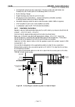
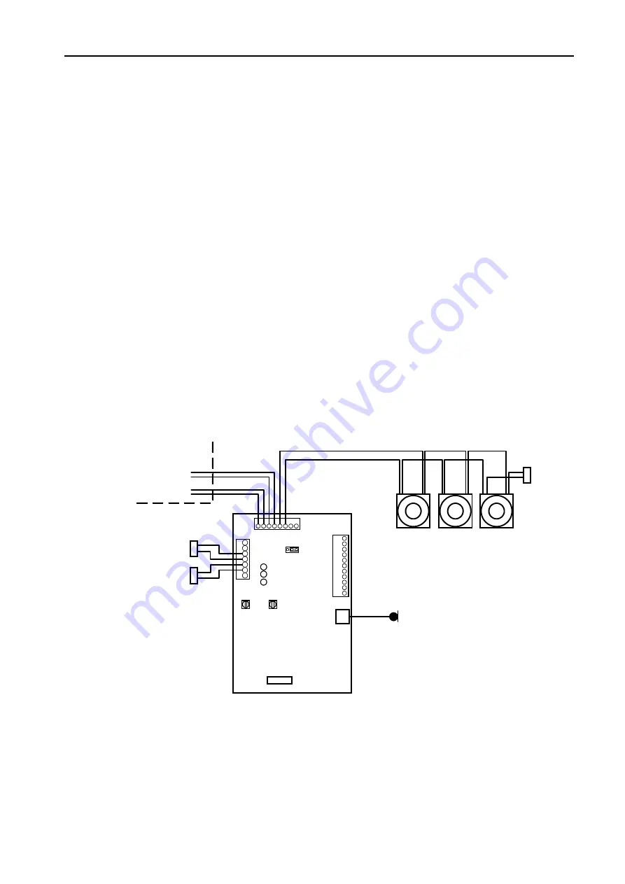
Speaker output is field-selectable between 25 and 70 volts by a jumper on the EVAX 25.
Jumper1 – 2 for 70 V and 2 – 3 for 25 V.
Connect only UL-approved speakers with a built-in line transformer.
Make sure to choose a speaker with appropriate voltage – 25 or 70 V. Select the
required power by connecting the appropriate branch in the transformer. Total power
requirements for all speakers will not exceed 25 Watts per amplifier.
Install a 2.4 K Ohm resistor at the end of the speaker output and a similar resistor in TB3
(connectors 5 – 6).
Connect the loudspeakers in the appropriate polarity to allow for line supervision.
Minimal battery size for the evacuation system is 4.5 AH 24 V for sites that do not have
an emergency generator.
24 V input to the EVAC25 will be from 24 V
DC
output from the control panel or from the
TPS34A remote power supply.
Trouble (yellow)
OK (green)
Alarm (red)
TB
1
TB
2
1
6
7
8
9
1
0
3
4
5
2
1
1
1
6 7 8
3 4 5
2
1
6
7
3
4
5
2
J2
2
1 3
Recording
gain
Playback
gain
TB3
Microphone P2
SN2
-
+
-
+
HORN
24 VDC OUT
2.4K EOL
resistor
ADR-3000
Loudspeaker
Loudspeaker Loudspeaker
2.4K EOL
resistor
5.1K EOL resistor from
the control panel
Figure 25 Connecting an evacuation system via General Output
– Page 19 –

