background image

Telefire


ADR-3000 – System Introduction 


Revision 1.10   4 November 2004 

2  Fire Alarm Control Panel 

2.1 Introduction 

The ADR-3000 control panel provides user-friendly operation.  The keyboard and the 
display that are mounted on the front panel contain an illuminated alphanumeric LCD, 
LED indicators for major events, and functional keys.  Access to all operations is 
secured by multi-level passwords. 
The interior section of the cabinet is secured by a key-lock.  It contains a power supply, 
the main board, line card(s), battery compartment space, and optional communication 
modules. 
The ADR-3000’s main board can contain one or two line cards, enabling control of as 
many as 508 addressable initiating devices, notification appliances and I/O modules. 
The ADR-3002 Single Loop Card controls as many as 127 addressable devices in a two-
wire Class B or Class A SLC loop. 
The ADR-3002C Dual Loop Card controls as many as 254 addressable devices in two 
two-wire Class B or Class A SLC loops. 
The system can be expanded beyond 508 addresses by networking.  An optional 
LON-3000 network communication module allows the connection of as many as 32 
control panels to set up a peer-to-peer network.  With appropriate programming each 
control panel on the network is able to respond to alarm and trouble events that occurred 
in other control panels. 
The control panel has an integral real time clock and calendar that enables day and 
night sensitivity setting for each analog detector according to weekly operation schedule 
and working hours.  Daytime and nighttime hours can be programmed independently for 
each day of the week. 
Events such as alarm, trouble, silencing, reset, programming, etc., are stored in the 
ADR-3000’s memory in the order in which they occur, creating event-list history.  An 
event record contains date, time, device type, and additional details.  Event records can 
be displayed on screen and printed as a report. 
All operations and configuration can be performed either from the system’s front panel or 
from a PC.  Telefire’s user-friendly proprietary programming and control software 
(running on Windows 98™ operating system) allows operators/installers to easily 
configure any system parameter using its advanced graphical interface. 

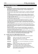
2.2  Components of the ADR-3000 Control Panel 

The basic system consists of the following components installed in the CAB-3000 
cabinet: 

CAB-3000


Analog control panel cabinet and battery compartment 

ADR-3001


Main board, containing one or two line cards 

ADR-3002


Single loop line card – as many as 127 addresses in a Class B or 
Class A loop 

ADR-3002C


Dual loop line card – as many as 254 addresses in two Class B or 
Class A loops 

ADR-3003


Display and keyboard module, mounted on the cabinet door 

ADR-4004TSW

  Switching power supply and battery charger module 

LON-3000


Communication module for system networking (Optional) 

NET-3000


Internet Enabled Monitoring and Notification Module (Optional) 

GIM-232


RS-232 isolation module that prevents ground fault when connecting 
grounded serial devices (Optional) 


– Page 2 – 

Summary of Contents for ADR-3000

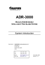
Page 1: ...M SYSTEM System Introduction Manufacturer TELEFIRE Fire Gas Detectors LTD 5 Halapid St P O B 7036 Petach Tikva 49250 Israel Tel 972 3 921 1955 Fax 972 3 921 1816 Email marketing telefire co il Web Site www telefire co il 4 November 2004 Revision 1 10 ...

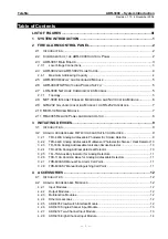
Page 2: ...ICES 9 3 1 INTRODUCTION 9 3 2 ANALOG ADDRESSABLE DETECTORS AND INITIATING DEVICES 9 3 2 1 TFO 440A Analog Addressable Photoelectric Smoke Detector 9 3 2 2 TPH 442A Analog Addressable Multisensor Photoelectric Smoke Heat Detector 10 3 2 3 TFI 330A Analog Addressable Ionization Smoke Detector 10 3 2 4 TFH 220A Analog Addressable Heat Detector 10 3 2 5 TFL 1NA Auxiliary Indicator for Analog Detectors...

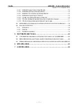
Page 3: ...ressable Indoor Alarm Notification Sounder 17 4 2 15 TPS 34A Analog Addressable Remote Power Supply 17 4 3 EPI 3000 ELECTROMAGNETIC AND SURGE PROTECTION INTERFACE MODULE 18 4 4 EVACUATION SYSTEM 18 4 4 1 Introduction 18 4 4 2 Features 18 4 4 3 Installation Guidelines 19 5 SOFTWARE AND TOOLS 22 5 1 TCS 3040 PROGRAMMING AND CONTROL SOFTWARE FOR THE ADR 3000 22 5 2 MCS 3000 CENTRALIZED FIRE ALARM SYS...

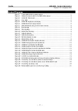
Page 4: ... flow 8 Figure 15 ADR 805 Flow Switch Interface Module 12 Figure 16 ADR 810 Single Channel Input Module 13 Figure 17 ADR 812 Two Channel Input Module 13 Figure 18 ADR 818 Eight Channel Input Module 14 Figure 19 ADR 820 Single Channel Output Module Interface 14 Figure 20 ADR 828 Eight Channel Output Module 15 Figure 21 ADR 823 Three Channel Input Output Module 15 Figure 22 ADR 833 Extinguishing Con...

Page 5: ...e control panel or a multi unit network Unlike conventional systems the ADR 3000 enables processing of analog signals received from detectors compensation of environment changes and drifts caused by dust accumulation while the alarm threshold setting values remains unaffected The system configuration allows considerable flexibility to in planning and installation starting as small as a single cont...

Page 6: ...d night sensitivity setting for each analog detector according to weekly operation schedule and working hours Daytime and nighttime hours can be programmed independently for each day of the week Events such as alarm trouble silencing reset programming etc are stored in the ADR 3000 s memory in the order in which they occur creating event list history An event record contains date time device type ...

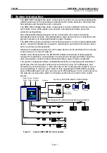
Page 7: ...r supply and easily accessible fuses are on the left side of the ADR 3001 board Alarm Trouble SLC loops and 24 VDC output for each loop card horn and dialer are on the bottom Connections to the keyboard and display board LON 3000 networking module an RS 232 port for NET 3000 PC printer the GIM 232 galvanic isolation modules or the MCID 34 modem and a connector for RM 4005 remote panels are located...

Page 8: ...card controls the bi directional communication between the control panel and the analog addressable devices on the SLC loop The loop is electronically protected against shorts and will be automatically disconnected if a short is sensed Each line card contains a loop fuse as a secondary protection Two LEDs for each loop indicate loop condition and serve installers and technicians The red LED flicke...

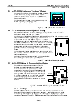
Page 9: ...5A L N The power cable should enter the control panel through either the top left or bottom left knockout hole Use a plastic bushing that fits the opening Connect the Live and Neutral wires to the proper terminal Connect the ground wire to the ground terminal Figure 6 ADR 4004 Power supply module 2 7 LON 3000 Network Communication Module The LON 3000 is a communication module that enables connecti...

Page 10: ...R 3000 ADR 3000 ADR 3000 ADR 3000 Termination Figure 10 Mixed free topology ADR 3000 LON 3000 LR 01 ADR 3000 LON 3000 LR 01 ADR 3000 LON 3000 LR 01 ADR 3000 LON 3000 LR 01 Ring Figure 9 Ring topology Please refer to the LON 3000 technical manual for further details 2 8 NET 3000 Internet Enabled Monitoring and Notification Module The ADR 3000 s internet enabled features allow it to provide fire ala...

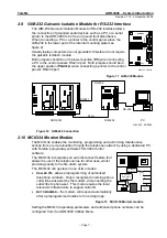
Page 11: ... VDC GIM 232 09 2004 Figure 12 GIM 232 Connection 2 10 MCID 34 Modem Module The MCID 34 enables the monitoring programming and performing maintenance actions from a remote location through the telephone network by using a dedicated PC with Telefire s proprietary software TCS 3040 control software J2 J1 PO J4 J3 To phone set To phone line socket RS 232 to main board COM 1 24 VDC in The MCID 34 inco...

Page 12: ...re pair RS 485 As many as 16 remote panels can be connected to the control panel using the same cable Each remote panel should be configured with a unique address of 1 to 16 The communication and input output circuits are fully supervised In large systems incorporating several control panels connected via a peer to peer network as many as 16 remote panels can be connected to each of the control pa...

Page 13: ...Analog Addressable Heat Detector fixed and rate of rise TFB 110A Common Base for Analog Addressable Detectors TFL 1NA Auxiliary Indicator for Analog Detectors TPB 800ASR Analog Addressable Indoor Manual Fire Alarm Call Point Red TPB 800ASY Analog Addressable Indoor Manual Extinguishing Call Point Yellow 3 2 1 TFO 440A Analog Addressable Photoelectric Smoke Detector Telefire s TFO 440A is an advanc...

Page 14: ...icroprocessor offers a high level of noise immunity The microprocessor also performs signal processing enables accurate control of the photoelectric chamber according to pre set parameters and manages the communication process with the control panel The TPH 442A detector excels in sensing smoldering smoke and differentiating between fires and false alarms due to other events that produce heat or s...

Page 15: ... Please refer to the TFL 1NA technical manual for further details 3 2 6 TFB 110A Common Base for Analog Addressable Detectors The TFB 110A is a standard common base that enables connection between Telefire s plug in analog detectors and a Telefire s analog addressable control panel The base is compatible with all of Telefire s Analog Addressable Detectors This base is intended for installation in ...

Page 16: ...ADR 805 Flow Switch Interface ADR 810 Single Channel Input Module ADR 812 Two Channel Input Module ADR 818 Eight Channel Input Module 4 2 2 Output Modules ADR 820 Single Channel Output Module ADR 828 Eight Channel Output Module 4 2 3 Multifunction Modules ADR 823 Three Channel Input Output Module ADR 833 Automatic Extinguishing Control Unit multi I O 4 2 4 Other Accessories LI 3000 Line Isolation ...

Page 17: ...810 Single Channel Input Module 4 2 7 ADR 812 Two Channel Input Module The ADR 812 is a two IDC dual channel input module that operates as an interface between the ADR 3000 analog addressable control panel and compatible two wire conventional initiating devices The two NFPA 72 Style C Initiating Device Circuits IDCs occupy two consecutive addresses The ADR 812 should be connected to a 24 VDC sourc...

Page 18: ...nd ADR 818 Eight Channel Input module can be connected to the following conventional Telefire detectors TFH 220F TFI 330 TFO 440 and TPH 442 Telefire may approve other compliant devices Figure 18 ADR 818 Eight Channel Input Module 4 2 9 ADR 820 Single Channel Output Module The ADR 820 enables the connection of output devices such as alarm bells horns extinguishers strobe lights etc through a singl...

Page 19: ...tic extinguishing functions The ADR 823 acts as an interface between an ADR 3000 analog control panel and conventional warning alarm and activating devices such as horns strobes automatic extinguishing devices pressure switches valves and flow switches The ADR 823 controls two 2 wire output lines The first NAC A works as a changed polarity and activates an additional dry contact alarm relay The ot...

Page 20: ... 833 requires a 24 VDC input t is supplied by the ADR 3000 or a TPS 34A Analog Addressable Remote Power Supply hat The ADR 833 occupies only a single address on the SLC loop although several inputs and outputs are connected to it Figure 22 ADR 833 Extinguishing Control Unit Please refer to the ADR 833 technical manual for further details 4 2 13 LI 3000 Line Isolation Module for Class A B The LI 30...

Page 21: ...ogrammer The sounder contains an alarm LED that is visible from 360 This LED flickers when polled by the control panel indicating normal operation During an alarm THE TIP 224A will sound interrupted beeps and the LED will flicker more rapidly and brightly than during normal operation The TIP 224A is intended for indoor use wherever there is a need for an indoor audible alarm Please refer to the TI...

Page 22: ...ed in order for the EMI shielding to work Card 1 SLC Loops 1 and 2 Card 2 SLC Loops 1 and 2 24 VDC A 24 VDC B Shield EPI 3000 Connections 07 2004 Figure 24 EPI 3000 Electromagnetic and Surge Protection Interface Module 4 4 Evacuation System 4 4 1 Introduction The EVAX 25 is an evacuation system that can be integrated with the ADR 3000 fire alarm system The system is powered and supervised by the a...

Page 23: ...oose a speaker with appropriate voltage 25 or 70 V Select the required power by connecting the appropriate branch in the transformer Total power requirements for all speakers will not exceed 25 Watts per amplifier Install a 2 4 K Ohm resistor at the end of the speaker output and a similar resistor in TB3 connectors 5 6 Connect the loudspeakers in the appropriate polarity to allow for line supervis...

Page 24: ...Trouble yellow OK green Alarm red Recording gain Playback gain Figure 26 Connecting an evacuation system via an Addressable Output Note SN2 8 must be off for all units without microphone TB1 TB2 1 6 7 8 9 10 3 4 5 2 11 1 6 7 8 3 4 5 2 1 6 7 3 4 5 2 J2 2 1 3 TB3 SN2 TB1 TB2 1 6 7 8 9 10 3 4 5 2 11 1 6 7 8 3 4 5 2 1 6 7 3 4 5 2 J2 2 1 3 TB3 SN2 To other evacuation systems Master Slave Microphone P2 ...

Page 25: ...X 25 ADR 3000 EVAX 25 EVAX 25 ADR 820 823 As many as 100 loudspeakers As many as 20 units EVAX 25 ADR 820 823 EVAX 25 ADR 820 823 As many as 100 loudspeakers As many as 100 loudspeakers As many as 100 loudspeakers Figure 28 Multi amplifier system in a multi storey building Page 21 ...

Page 26: ...cluding normal operation alarm and trouble For security reasons the MCS 3000 does not allow remote control activations of fire alarm control panels A single screen can display system summary of a large number of systems Clicking on any of the systems will open a browser window that will display the web page for that system Please refer to the MCS 3000 manual for further information 5 3 PROG 4000 A...

Page 27: ...ies in capacity of up to 12AH The battery enclosure can contain two 12 V sealed lead acid batteries up to 20 W by 7 D by 12 H cm each For fire alarm control panels requiring batteries that will not fit in the ADR 3000 chassis use the BC 3000 external battery enclosure This enclosure can contain two 12V sealed lead acid batteries up to 20 W by 10 D by 15 H cm each If the system requires battery cap...

Page 28: ...r 2004 Page 24 7 Certification Telefire s ADR 3000 Analog Addressable Conventional Fire Alarm Control Panel has the following approvals SI 1220 Approved EN 54 Approved BS EN 54 Approved CP 10 Approved GOST 26342 82 Approved GOST 27990 88 Approved UL 864 Compliant ...

Reviews: