Telefire
ADR-3000 – System Introduction
Revision 1.10 4 November 2004
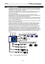
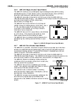
MCID-34
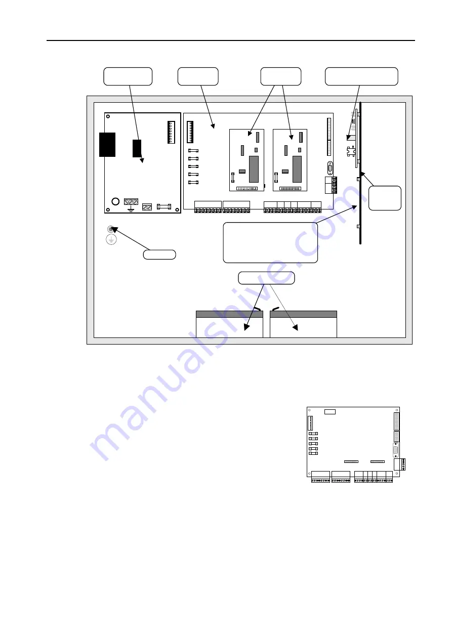
Modem Module (Optional)
ADR-3000 Chassis 09/2004
Backup Batteries
Card 1
Card 2
Ground
ADR-4004TSW
Power Supply
ADR-3001
Main Board
ADR-3002
Line Cards
LON-3000
Communication Module
Internal
Mounting
Plate
Lower expansion slot for one of the
following optional modules:
o
NET-3000
o
GIM-3000
o
MCID-34
POWER OUT
JP2
Batteries
F1
6.3A
L
N
Figure 2
Internal module location in the ADR-3000 cabinet
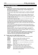
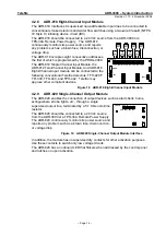
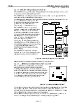
2.3 ADR-3001 Main Board
The ADR-3001 main board is designed for ease of maintainability. Connectors are
located in logical groups. Power input from the power
supply and easily accessible fuses are on the left side of
the ADR-3001 board. Alarm, Trouble, SLC loops and
24 V
DC
output for each loop card, horn and dialer are on
the bottom. Connections to the keyboard and display
board; LON-3000 networking module; an RS-232 port for
NET-3000, PC, printer, the GIM-232 galvanic isolation
modules, or the MCID-34 modem; and a connector for
RM-4005 remote panels are located on the right.
ADR 3001 09/2004
Figure 3
ADR-3001 Main board
2.3.1 Low-Voltage
Connections
The ADR-3000 can interface and activate various output devices that are connected to
the addressable loop or directly to the control panel’s general outputs as follows:
Alarm outputs
Two sets of dry contacts and a programmable level activated
supervised output.
Trouble outputs
Dry contacts and a level activated supervised output.
– Page 3 –

