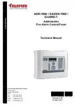
ADR-7000 / SAVER-7000 / GUARD-7
© 2017
– Telefire Fire & Gas Detectors Ltd
Revision 0.98 October 2017
– Page 4 of 87 –
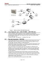
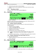
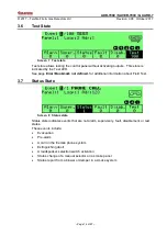
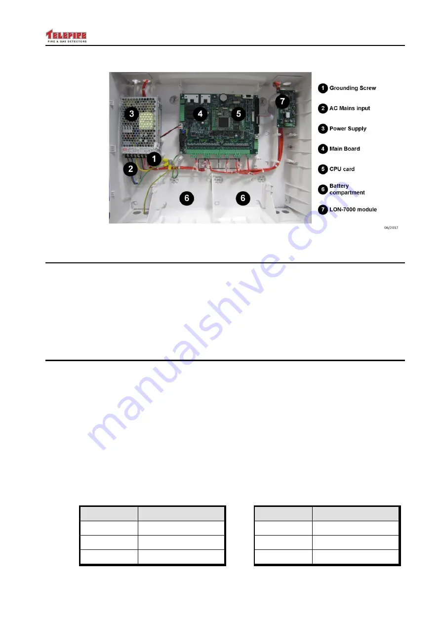
Figure 1 Schematic ADR-7000 subassemblies
2.1
Main Board
– ADR-7021
The ADR-7000's ADR-7021 main board is designed for ease of installation and
maintenance. Connectors are located in logical groups; on the left are the input from the
power supply and battery connection; three dry contact relays; and a connector for
changing the addresses of addressable modules. On the bottom are the two general
purpose NACs; SLC loops; 24Vdc supply to the field; and dialer activation and voltage
supply. On the right are the display / keyboard connector; LON-7000 networking
module; an RS-232 port for NET-7000 TCP/IP module, and a connector for the remote
annunciator units.
2.2
SLC Line Card
– ADR-7002
Up to four ADR-7002 line cards line cards are mounted on the ADR-7021 main board
and control the bi-directional communication between the control panel and the
addressable devices on the SLC loop.
The loop is electronically protected against shorts, and will be automatically
disconnected if a short is sensed. Each line card can be configured to work in a Class B
or Class A loop.
Two LEDs for each loop indicate loop condition and serve installers and technicians:
The red LED flashes each time a device is addressed
The yellow LED flashes when a fault is detected, even after a momentary
interference that would not activate a trouble condition
2.2.1 Maximum Addresses
– ADR-7000
All loop cards are capable of communicating with up to 127 addresses, and the
maximum number of addresses is a 1,016 single control panel.
Line Cards
Max. Addresses
Line Cards
Max. Addresses
1
127
5
635
2
254
6
762
3
381
7
889

