ADR-7000 / SAVER-7000 / GUARD-7
© 2017
– Telefire Fire & Gas Detectors Ltd
Revision 0.98 October 2017
– Page 21 of 87 –
4.3
Wiring
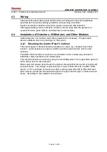
Cable selection and cabling work shall be done according the rules and regulations
specified by the authority having jurisdiction and planning consultant.
System connections shall be done when power sources are disconnected.
Changing/installing electric activation modules shall be done after the system is in
quiescence state (push buttons and detectors in normal state).
4.4
Installation of Detectors, I/O Modules, and Other Modules
Install detectors, I/O modules, and other equipment as necessary. Program each
device’s address prior to connecting it to the system.
4.4.1 Mounting the Control Panel's Cabinet
The control panel’s cabinet should be installed in a clean, dry, vibration-free indoor
location. Avoid exposure to severe conditions such as high humidity, dust and air
pollution.
The ADR-7000 should be mounted on a solid wall in order to allow easy access for
installation, daily operations and maintenance.
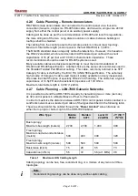
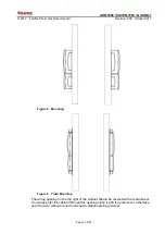
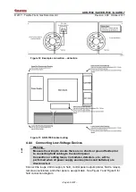
The cabinet should be mounted by using the two sliding slots on the upper back part of it
and a screw hole on the lower part.
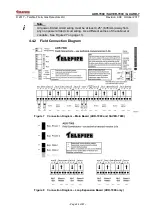
Mains input (AC power) should enter the cabinet through either the top left or bottom left
knockout holes. Low voltage connections (SLC loops; 24Vdc; RS-232 to a NET-7000,
printer, or PC; LonWorks connection to other control panels; RS-485 to RM-7000; and
NAC outputs) should be connected through the top right, bottom right, or back knockout
holes
– according to the installer’s convenience.

