LI-3000 / LI-3000E
© 1999
–
2015 Telefire Fire & Gas Detectors Ltd
Revision 1.14 May 2015
– Page 4 of 6 –
4.1.3 Cabling Planning – Signaling Line Circuits (SLC)
The module connects to the control panel via a two-wire cable 12 – 18 AWG (cross
section of 0.8mm
2
to 3.3mm
2
). Twisted-pair cable is recommended.
Wire Size
Cross Section (mm
2
)
Maximum SLC branch length for wire size
18 AWG
0.8 mm
2
950 m
16 AWG
1.3 mm
2
1,520 m
14 AWG
2.1 mm
2
2,420 m
12 AWG
3.3 mm
2
3,830 m
Table 1
Selecting SLC Wires
4.2
Installing the LI-3000
4.2.1 Address Programming
The module's address should be programmed prior to installation by connecting the
PROG-4000 unit to connector JP1 (please refer to the PROG-4000 manual for further
details on address programming).
4.2.2 Configuring the ADR-3000
When configuring the line card from the control panel, open the “
System Config
” menu,
move the cursor to the “
Card
” field, and press the up or down key as necessary to select
the appropriate line card.
Switch between Class A and Class B by pressing the
Enable
key. Press the
Enable
key again to switch between Class A and Class B again. To disable the line card press
the
Disable
key.
To add an Isolator module to the system, select the manual device programming screen
in the control panel, move the cursor to the “
Type
” field and select
Isolator
by pressing
the up or down keys. Make sure the Isolator’s address was programmed prior to
installation. Please refer to the ADR-3000 technical manual for additional details on
system programming.
4.2.3
Connecting the SLC
Connect the SLC from the control panel or previous device to the SLC L side of the
LI-3000. Connect the SLC to the next device from the SLC R side of the LI-3000.
4.2.4 Connecting Wiring
Use an anti-static ground wrist-strap when handling any system circuits to prevent static
discharge to the modules.
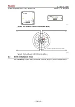
Connect the incoming SLC wires to SLC L and the outgoing SLC wires to SLC R.
Connect all wires according to marked polarity (see Figure 3).
All wiring must conform to applicable local codes, ordinances and regulations
i
Note
Measure the wiring to ensure there are no shorts before connecting the wiring
to the control panel.
Connecting or adding zone, devices, outputs etc shall be done when all
power to the control power (AC and batteries).


