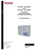
TSA-200 / TSA-200XT / TSA-240 / TSA-240XT
© 2010 –
2014 Telefire Fire & Gas Detectors Ltd
Revision 1.06 July 2014
– Page 5 of 53 –
Hence the TSA-200 product family has the UL 864 edition 9 human interface
characteristics, makes, as well as being EN 54-2 and EN 54-4 certified.
NOTE!
IF an
EN 12094-1 certified
CIE/CDE (EXTINGUISHING CONTROL PANEL) IS
REQUIRED, PLEASE CONTACT TELEFIRE Ltd. ABOUT AVAILABLE PRODUCTS.
3.9
Suitability of use in various environments
3.9.1 Environmental Limits and Protection Level
The TSA-200 product family environmental limits are specified in EN-54-02:1998
paragraph 12.
The TSA-200Product family is specified for -5°C to +40°C temperature range, RH max
95%, and IP30 protection level.
i
Note
See
Routing cables into the ECD and maintaining the protection level
page 25, for
information about maintaining the protection level.
i
Note
Do not operate the ECD outside the specified limits.
3.9.2 Suitable Environment
The TSA-200 product family environmental limits are stated above. It is to be installed in
an indoors location, well ventilated location, protected from the elements.
Avoid locating the CP in direct sunlight or near sources of heat.
It is recommended to install the CP in an electrically quiet location (i.e. away from high
power cables, motors, etc).
3.10
Limiting the Consequences of Faults
See
Power Supply, Charger and Batteries
, page 22, for explanation of PS/Charger
limiting/protection devices.
The Main Board, which contains the charge control circuitry and the battery protective
resettable PTC, also has a common electronic limiter for most output ports (It does not
protect the contacts of relays!), which are monitored by the CPU
If there is an overload on an output (or outputs), the common limiter shuts off, the buzzer
sounds and the visual fault indication and the Fault relay are switches ON. The CPU
switches OFF all the controlled outputs. It then switches ON the separate outputs in
sequence, until the faulty output is isolated. All "good" outputs are then switched ON,
except for the faulty outputs.
The controlled outputs (i.e. all outputs except relays' contacts or OC outputs) are
continuously monitored.
Recovery from faults is detected by the CPU and all relevant recovered outputs are
reactivated, if necessary.
Open Collector outputs are current limited by design, by series connected high value
resistors.
NOTE! The control panel shall be powered by a dedicated mains circuit with its own
circuit breaker.

