TSA-200 / TSA-200XT / TSA-240 / TSA-240XT
© 2010 –
2014 Telefire Fire & Gas Detectors Ltd
Revision 1.06 July 2014
Page 19 of 79
7.4
Current Calculations and Allocation
Allocating the output currents to specific ports when the CP is in Alarm is required, so
devices can function correctly, while the 1.5A PS limit is not violated.
i
Note
Charging is stopped in the alarm state; hence the charge current is ignored in
the Alarm state current calculations.
The extinguisher has priority over other outputs, and the CP internally draws 0.16A. (See
the Tech Specs above). Hence the current for the remaining devices is 1.5-0.16-
extinguisher current, or 1.34A – Extinguisher current. Allocate the remaining current
between the other devices, according to their priority. If the total 1.5A limit is not violated,
and the maximum current drawn from of each single output is below its allowed limit, you
can add devices (such as multiple sounders, strobes, etc), provided that each single
output limit is not violated, and the total PS load current in the alarm state (sum of the
ECD internal and load
currents) does not exceed 1.5A!
7.5
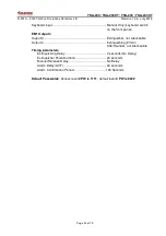
Default Ports Allocation and ECD Configuration
Main Board (TSA-200MB)
Inputs
Inputs 1, 2 ..................................................................... Detector zone (Default:
Unverified
)
Outputs:
Output 1 ........................................................................ Fire Alarm sounder,
Silenceable
Output 2 ....................................................................... FARE (Fire Alarm Routing
Equipment) dialer output.
Not
Silenceable
Fault Dialer (named FWRE) ......................................... FWRE Output,
not delayed, not
silenceable.
MB OC
Open Collector Outputs
OC 1 ............................................................................. Transmit the information of zone
1 alarm
OC2 .............................................................................. Transmit the information of zone
2 alarm
MB Relays
Relay 1 ......................................................................... General Fire Alarm Relay
Relay 2 ………………………………………………………General Fault Relay
EM1 expansion module [TSA-200XT / TSA-240 / TSA-240XT]
EM1 Inputs:
Input 3........................................................................... Pressure switch
Input 4........................................................................... Manual release (Manual
Extinguishing Trigger)
Input 5........................................................................... Inhibit (Hold/Abort) switch


