TSA-200 / TSA-200XT / TSA-240 / TSA-240XT
© 2010 –
2014 Telefire Fire & Gas Detectors Ltd
Revision 1.06 July 2014
Page 31 of 79
Verify that all power sources to the ECD are disconnected.
Disconnect the ECD AC cable from the mains, so that the ECD ends of the wires can be
handled safely.
Insert the AC input power cable to the control panel enclosure through either the top left
or bottom left knockout opening and keep it separated and distant from the field wiring
and the control panel circuits.
Use appropriate bushing/grommet that fits the knockout openings, to ascertain that there
are no sharp edges, to prevent damage or abrasion to the cable during assembly and
use.
Remove the PS terminals protective cover (RED) and keep it and its screw for
reassembly
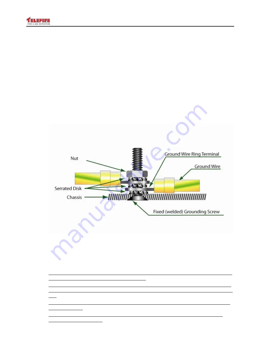
CONNECT THE GROUND WIRE OF THE AC INPUT CABLE (Yellow Green wire) and
the (short) Yellow/Green PS ground wire DIRECTLY THE PANEL'S CHASSIS
GROUND SCREW, USING SERRATED WASHERS AS SHOWN.
Figure 8 Connecting the grounding wires to the Chassis
Connect the end of the PS (short, Yellow /Green) GND wire to the PS GND terminal
Then connect the Line and Neutral wires to the proper PS terminals. Tighten the terminal
block screws.
9.8.2 Connecting the batteries
Place and connect batteries in the Control Panel, only after the Control Panel is properly
installed and is in the correct (upright) position.
Place batteries so they are adjacent to the back of the Control Panel enclosure, with the
batteries terminals in the UP (TOP) position, as shown in the appropriate drawings in the
TM.
Place protective covers on batteries' terminals when the battery wires are disconnected
from the battery.
Remove batteries (after assembling protective terminals covers) from the CP before
moving the Control Panel.

