-51-
Shown as figure 58, for the alarm information setting on the right column, users can configure the Trap
switch, Panel switch, and the log level.
Trap:
when it is ON, IDH2-3000 Series will send the trap information to server through SNMP.
Panel:
when it is ON, the alarm light on the front panel of IDH2-3000 Series will display the alarm.
Log Level:
set level of severity for the alarm, from lowest to highest level: disable, info, warning,
critical. SNMP will judge the severity of the alarm depending its log level.
When finish the settings, click “Submit” button to validate them.
【
Remark
】
The realization of Trap and log level is relate to the SNMP, for specific instructions, see the
SNMP user manual.
§
§
3
3
.
.
2
2
.
.
8
8
.
.
1
1
.
.
2
2
S
S
t
t
a
a
t
t
u
u
s
s
M
M
o
o
n
n
i
i
t
t
o
o
r
r
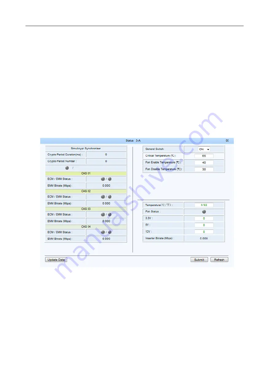
Shown as figure 59
, click “status” button to enter the module status page, shown as below:
Fig.59
Daughter Board Status Page
Shown as figure 61, the right column is for the temperature alarm setting, including general switch,
critical temperature, and fan active/inactive temperature. The left column shows the communication
status between the current module and the CAS.
General Switch:
choose between ON/OFF to enable/disenable the temperature alarms. Click
“Submit” to validate the setting.
Critical Temperature:
set the upper limit temperature, click “Submit” to validate the setting.
Fan Disable Temperature:
set the upper limit temperature of the fan. Then the temperature is
higher than this setting temperature, the fan will start to work. Click “Submit” to validate the setting.
Fan Enable Temperature:
set the lower limit temperature of the fan. When the temperature is lower
tha
n this setting temperature, the fan will stop working. Click “Submit” to validate the setting.


