
Programmable Sweep Instruction Manual
INSTALLATION
telemark.com
18 of 58
Rev 1.0.0
Ambient temperature.
Exceeding the maximum permitted ambient temperature may damage
the device.
Make sure that the maximum permitted ambient temperature is not
exceeded. Do not expose the device to direct sunlight.
Protection class of the rack.
If the product is installed in a rack, it is likely to lower the protection class
of the rack (protection from foreign bodies and water) e.g. according to
the EN 60204-1 regulations for switching cabinets.
Take appropriate measures to restore the required protection class of
the rack.
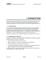
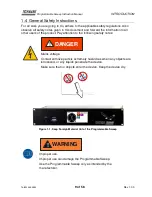
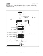
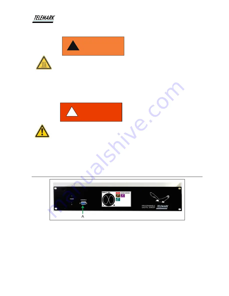
3.4 Controller Connecting
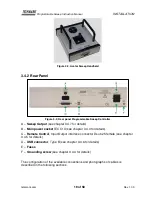
Figure 3-1, Front Panel Connection
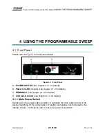
3.4.1 Front Panel
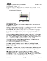
A
–
Handheld, Avatar Joystick Sweep Remote Control Connection
The Handheld can be used when needed and removed when not needed.
WARNING
!
DANGER
!


