Appendix A
8-Port Expansion Module Option
56 OMEGA Installation, Operation, and Maintenance Manual
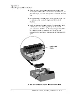
3.
Insert the cable clip into the round hole next to the relays
labeled K2 and K3 on the component side of the Module. Use
this cable clip to route and arrange cables within the OMEGA
unit.
4.
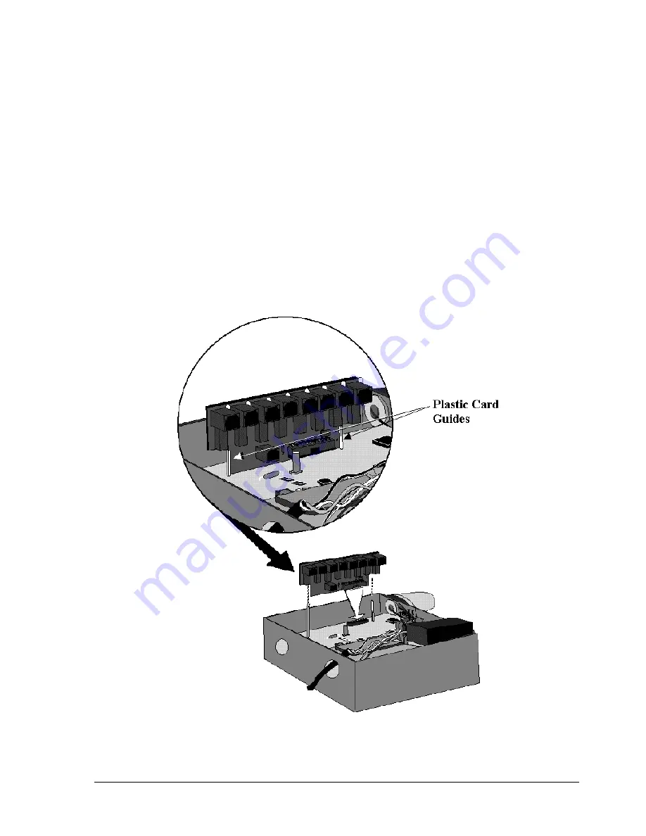
Hold the Module vertically above the card guides, so its 8 RJ-
11 jacks are at the top and facing toward the inside of
OMEGA.
5.
Insert the Module into the card guide slots and slide it down
until the male connector engages fully into the female
connector on the OMEGA baseboard (see Figure A-1). This
installation can only be made one way. If you are not
successful with your first try, turn around the Module and try
again.
Firgure A-1. Sliding the Module into the Card Guides
Summary of Contents for OM-AMPS-100
Page 6: ...Table of Contents vi OMEGA Installation Operation and Maintenance Manual Notes...
Page 10: ...Preface 10 OMEGA Installation Operation and Maintenance Manual Notes...
Page 12: ...Section 1 Contents 12 OMEGA Installation Operation and Maintenance Manual...
Page 24: ...Section 1 Contents 24 OMEGA Installation Operation and Maintenance Manual Notes...
Page 26: ...Section 2 Contents 26 OMEGA Installation Operation and Maintenance Manual...
Page 30: ...Section 3 Specifications OMEGA Operation and Maintenance Manual 30...
Page 36: ...Section 3 Specifications 36 OMEGA Installation Operation and Maintenance Manual Notes...
Page 38: ...Section 4 Using the Configuration Program OMEGA Operation and Maintenance Manual 38...
Page 46: ...Section 5 External Antenna Guidelines 46 OMEGA Installation Operation and Maintenance Manual...
Page 64: ...Appendix B Warranty Compliances 64 OMEGA Installation Operation and Maintenance Manual...

