background image


BenchMark

®

200/BM470 Marking System


34743A 

5 of 8 

BM470 CONTROLLER 

Specifications 

The BM470 Controller specifications are subject to change 
without prior notice. 

Compliance ...........................  CE, RoHS 

Rating  ...................................   NEMA 1  (I.P. 30)  

Mounting Configuration .........   Table-top 

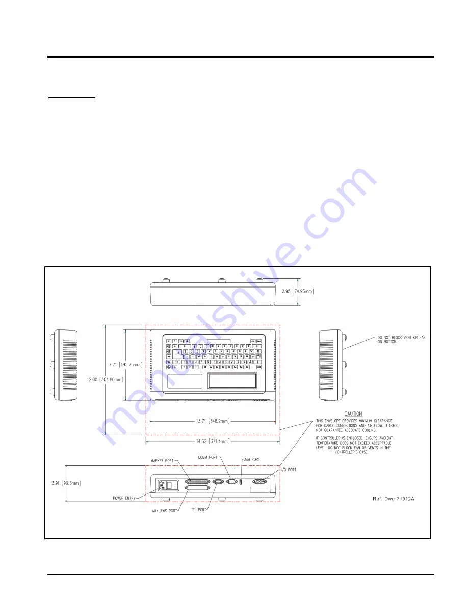
Dimensions ...............................  see 

BM470 Controller Dimensions


drawing for details 

Weight  ..................................   1.68 Kg (3.69 lb.) controller only 

Power Requirements ............  95 to 250 VAC, 2 amps, 50-60 Hz, 

single phase 


Operating Temperature ........   0° to 50°C (32° to 122° F),  

non-condensing 

Operating Humidity ...............   10% to 80% non-condensing 

Cooling .....................................   Internal, thermostatically-controlled fan 

Communications ...................   TTL, RS232, and USB * 

Input Signals ** ........................  Two available (Start Print, Stop/Abort) 

10 VDC (minimum voltage) 
30 VDC (maximum voltage) 
12 to 24 VDC (nominal voltage) 
2.3 mA @ 12VDC; 4.9 mA @ 
24VDC (nominal current) 

*

*  USB for data backup & transfer 

**  Additional I/O signals available with the optional  

BM470+ Enhanced Communications Software


BM470 Controller Dimensions 

Summary of Contents for BenchMark 200

Page 1: ...nd direct drive toothed pulleys The pin design permits high quality consistent marks on irregular slightly curved surfaces It also accommodates applications where marking surfaces cannot be positioned at a consistent distance from the marker The Marker Cable connects the marker to the BM470 Controller The cable is 4 m 13 ft long and is pre wired to the marking head The Pin Cartridge machined from ...

Page 2: ...on controller power switch to ON on back panel to start the marking system software 7 Adjust pin stroke for proper pin impact depth BENCHMARK200 MARKING HEAD Specifications The BenchMark200 marking head specifications are subject to change without prior notice Dimensions see BenchMark200 Marking Head Dimensions drawing for details Weight 5 63 Kg 12 375 lb marker cable 5 08 Kg 11 185 lb marker only...

Page 3: ...heavily dependent on the part being impacted Conditions such as the material being marked the rigidity of the work piece machine settings ambient noise etc may all vary when in operational use Such variables will alter the actual noise level Despite detailed guidance provided with each machine variable operating conditions are beyond the control of Telesis The responsibility of establishing safe w...

Page 4: ...ations are subject to change without prior notice Dimensions H x W x D 686 0 x 270 0 x 414 0 mm 27 0 x 10 63 x 16 29 in Height Adjustment 298 4 mm 11 75 in with standard 25XLE pin cartridge Weight 13 9 Kg 30 5 lb Additional Features see BenchMark Tool Stand Dimensions drawing for details BenchMark Tool Stand Dimensions ...

Page 5: ...ements 95 to 250 VAC 2 amps 50 60 Hz single phase Operating Temperature 0 to 50 C 32 to 122 F non condensing Operating Humidity 10 to 80 non condensing Cooling Internal thermostatically controlled fan Communications TTL RS232 and USB Input Signals Two available Start Print Stop Abort 10 VDC minimum voltage 30 VDC maximum voltage 12 to 24 VDC nominal voltage 2 3 mA 12VDC 4 9 mA 24VDC nominal curren...

Page 6: ...n or foot pedal switch These types of devices can remotely control Start Print and Stop Abort Print operations Comm Port allows connection to a remote serial device The Comm port may be used to connect an optional customer supplied PC to access Telesis software utilities Utility software may be used to backup patterns stored in the controller to download a custom font to the controller or to downl...

Page 7: ...ontroller Asynchronous 1200 2400 4800 9600 19200 38400 or 115200 Baud 1 or 2 Stop Bits 7 or 8 Data Bits None Even or Odd Parity Host Communications continued In addition defining Comm Port communication parameters you can select the type of protocol to be used Extended Protocol or Programmable Protocol Programmable Protocol Use this protocol where very simple one way communications are required su...

Page 8: ...ut and input signals The system will return a hexadecimal code for the 6 output signals and 12 input signals in the following format O O I I I where bit 1 READY 0x01 bit 2 DONE 0x02 bit 3 PAUSED 0x04 bit 4 NO_FAULT 0x08 bit 5 SPARE_1 0x10 bit 6 SPARE_2 0x20 bit 1 START 0x001 bit 2 STOP 0x002 bit 3 SEL_0 0x004 bit 4 SEL_1 0x008 bit 5 SEL_2 0x010 bit 6 SEL_3 0x020 bit 7 SEL_6 0x040 bit 8 SEL_4 0x080...

Reviews: