•
w.pxf.lscxv52
•
w.pxf.lscxss7
•
w.pxf.lscxdss
•
w.pxf.lscxcas
Number of units per system
There can be only one DFF card in any type per system.
Location
Main cabinet (2.pxf.urnxmkn or 2.pxf19inmkn), the first slot to the right of the power
supply unit. Mounted over the control and switching unit (2.px0.ipbxdfl).
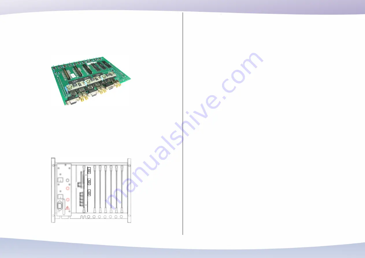
1.px0.dffx4e1
Description
1.px0.dffx4e1 is a 2.048 Mbit E1 (ITU-T G.703) digital interface card providing four
E1s. The E1s can connect to 120 ohm balanced (or optional 75 ohm unbalanced)
terminations. The clock of the PX24X Hybrid IP PBX can be programmed to
synchronize with any of the E1s or it may run freely. The line code is programmable
as AMI or HDB3. Cyclic redundancy check (CRC4) can be enabled or disabled
for each E1 interface individually. The direction of each channel of each E1 can be
programmed as incoming, outgoing, both-way, or unavailable and therefore yields
fractional E1 connections. The types of signaling / protocol available for the E1
interfaces are:
•
Channel-Associated Signaling (CAS)
•
Single-bit E&M emulation
•
Two-bit ITU-T R1
•
Two-bit ITU-T R2
•
Many variations of signaling types (such as CL-1B, OCL-1B, TCL-
1B, SL/ZSL, SLM) widely employed in CIS countries
•
Common-Channel Signaling (CCS)
•
DSS1 (Euro-ISDN in the TE direction)
•
DSS1 (Euro-ISDN in the NT direction)
•
ECMA QSIG (in the TE direction)
•
ECMA QSIG (in the NT direction)
•
ITU-T Signaling System No.7 ISUP
•
V5.2 LE and AN protocol
In addition to E1 interfaces, the card provides circuits to drive up to three auxiliary
cabinets in a system.
License
Each E1 interface requires one of the following licenses for the signaling / protocol
support.
16


