INSTALLATION INSTRUCTION CSM 113
Access Systems
LU
March 16, 1998
1(2)
T:\CFO\INSTALL.ENG\CFO700\CSM113.DOC
DUAL SUBCARRIER MODULATOR
CSM 113
PRE-INSTALLATION ADJUSTMENTS
(DIP SWITCHES)
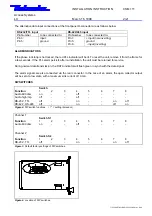
-Data/audio input selection
-Data format selection
-Audio input impedance 600/high selection
(see Figures 2 and 3.)
Note! Each channel has a separate DIP switch
INSTALLATION
The module is to be pushed along the guide rails into
the CSR-series installation frame, and secured with
the locking screws (2 pcs). The unit should be posi-
tioned on the left-hand side of a CVM 201 FM video
modulator.
CONNECTIONS
The upper D-connector is assigned to channel 1 (sub-
carrier 7.02 MHz) and the lower D-connector for chan-
nel 2 (sub-carrier 7.20 MHz). Male D-connectors are
used.
AUDIO SIGNAL
If the input signal is an audio signal, set the DIP-
switches to the desired input according to the AUDIO
600 OHM setting (see Figure 2). If necessary, the
audio input impedance can be set to the “AUDIO
HIGH IMPEDANCE” position. The nominal audio input
level is 0 dBm (symmetrical input) and -6 dBm (asym-
metrical input).
The overload margin is 6 dB.
The alternative audio input connections in the front panel D-connector are as follows below:
Symmetrical Input
Asymmetrical Input
Pin Number
to be connected to:
Pin Number
to be connected to:
Pin 5:
ground
Pin 5:
ground
Pin 8:
+ input
Pin 8:
+ input
Pin 9:
– input
Pin 9:
ground
DATA SIGNAL
If the input signal is a data signal, the unit’s DIP switches should be set for the desired input, (either in the
RS-232/TTL or RS-422/485 position,) according to the data format. The RS-232 input is also compatible
with TTL-level signals. The maximum bit rate for input signals is 20 kbit/s.
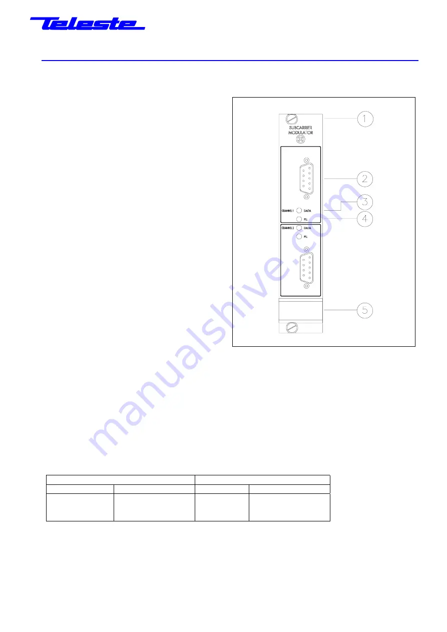
Figure 1. The CSM113
1) Locking
screw
2) Audio/data input, D9 female
3) Data indicator for channel 1
4) PLL alarm indicator for channel 1
5) Handle


