background image


User Manual 

CXE180 


59300401 

Rev.001 


26.5.2010 

8(12) 


Front panel 

8910051


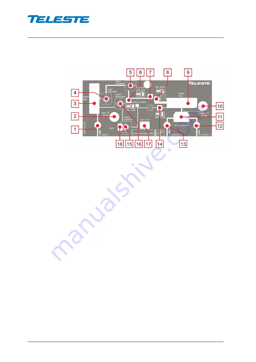
Figure 4. CXE180 Front panel 


1)  RF input 

2)  Input test point, -20 dB 

transformer 

3)  Input diplex filter 

4)  Input attenuator 

5)  Input equaliser 

6)  Cable simulator *) 

7)  Mid stage gain selection 

jumper *) 

8)  Mid stage slope selection 

jumper *) 

9)  Output diplex filter 

10)  Output test point, -20dB 

directional coupler 

11)  Output module (see table 1) 

12)  RF output 1 

13)  RF output 2 

14)  Return path input attenuator 

*) 

15)  Return path equaliser 

16)  Return path attenuator 

17)  Remote powering jumper for 

outputs *) 

18)  Remote powering jumper for 

input *) 


*) See chapter ‘Jumper settings’ 

Summary of Contents for CXE180

Page 1: ...User Manual CXE180 59300401 Rev 001 26 5 2010 1 12 CXE Series User Manual Teleste Corporation CXE180 Universal amplifier...

Page 2: ...10 2 12 Contents Introduction 3 Technical specifications 4 Block diagram 5 Installation 6 Housing 6 Interfaces 6 Powering 7 Front panel 8 Jumper settings 9 Adjustments 10 Downstream signal path 10 Ups...

Page 3: ...upstream Adjustments use electrical controls thus eliminating the need of the usual plug in attenuators in the system set up Other standard features include reliable power supply built in US amplifier...

Page 4: ...ath return module and diplex filters are installed into the CXE202 Frequency range 5 30 42 50 65 85 MHzMHz Return loss 18 dB Gain 28 0 dB Gain control range output 0 15 dB 1 dB Gain control range inpu...

Page 5: ...User Manual CXE180 59300401 Rev 001 26 5 2010 5 12 Block diagram IN dB Sloped Flat dB 10 dB 0 dB OUT 1 TP 20dB AC AC OUT 2 High gain Low gain Flat Cable simulation AC TP 20dB...

Page 6: ...hen closing the cover use a PZD 2 screwdriver to tighten the bolt to a torque of 2 5 3 5 Nm To ground the amplifier housing connect at least 4 mm 2 grounding wire Cu from a proper earth to the groundi...

Page 7: ...es installation by an instructed person Because the amplifier is not equipped with an all pole mains switch the powering shall be carried out in accordance with all applicable installation rules The p...

Page 8: ...er 6 Cable simulator 7 Mid stage gain selection jumper 8 Mid stage slope selection jumper 9 Output diplex filter 10 Output test point 20dB directional coupler 11 Output module see table 1 12 RF output...

Page 9: ...in selection mid stage slope selection and return path attenuation Cable simulator jumper Figure 4 pos 6 Mid stage gain selection jumper Figure 4 pos 7 Mid stage slope selection jumper Figure 4 pos 8...

Page 10: ...output test point Figure 4 pos 10 Make final adjustment of the output slope with the variable input equaliser Figure 4 pos 5 If you are having trouble obtaining the expected output level then check th...

Page 11: ...ath ends normally at the Head End HE or at Hub Start adjustment with the first amplifier nearest to the headend The upstream signal path requires a specific signal level for proper operation The ideal...

Page 12: ...y special incidental consequential or indirect damages howsoever caused The contents of this document are provided as is Except as required by applicable law no warranties of any kind either express o...

Reviews: