Telesteps Loft Ladder adjustment instructions
Introduction
These instructions must be followed when there is a requirement to configure
loft ladder models 60924, 60927 and 60330 to individual floor to ceiling heights
and adequate operating angles
When the loft ladder is initially fitted, the ladder is configured to the lowest floor
to ceiling height within the range of the purchased loft ladder (i.e. 2.35m In the
case of the 60924 model). If this factory set ladder length is correct for your
particular installation then no further action is required.
However if adjustment is required the adjustment instructions should be
followed to extend the ladder length to suit your particular floor to ceiling height
and to gain a comfortable angle for its continued use.
Tools required
1x Small flat bladed screwdriver
Component Identification
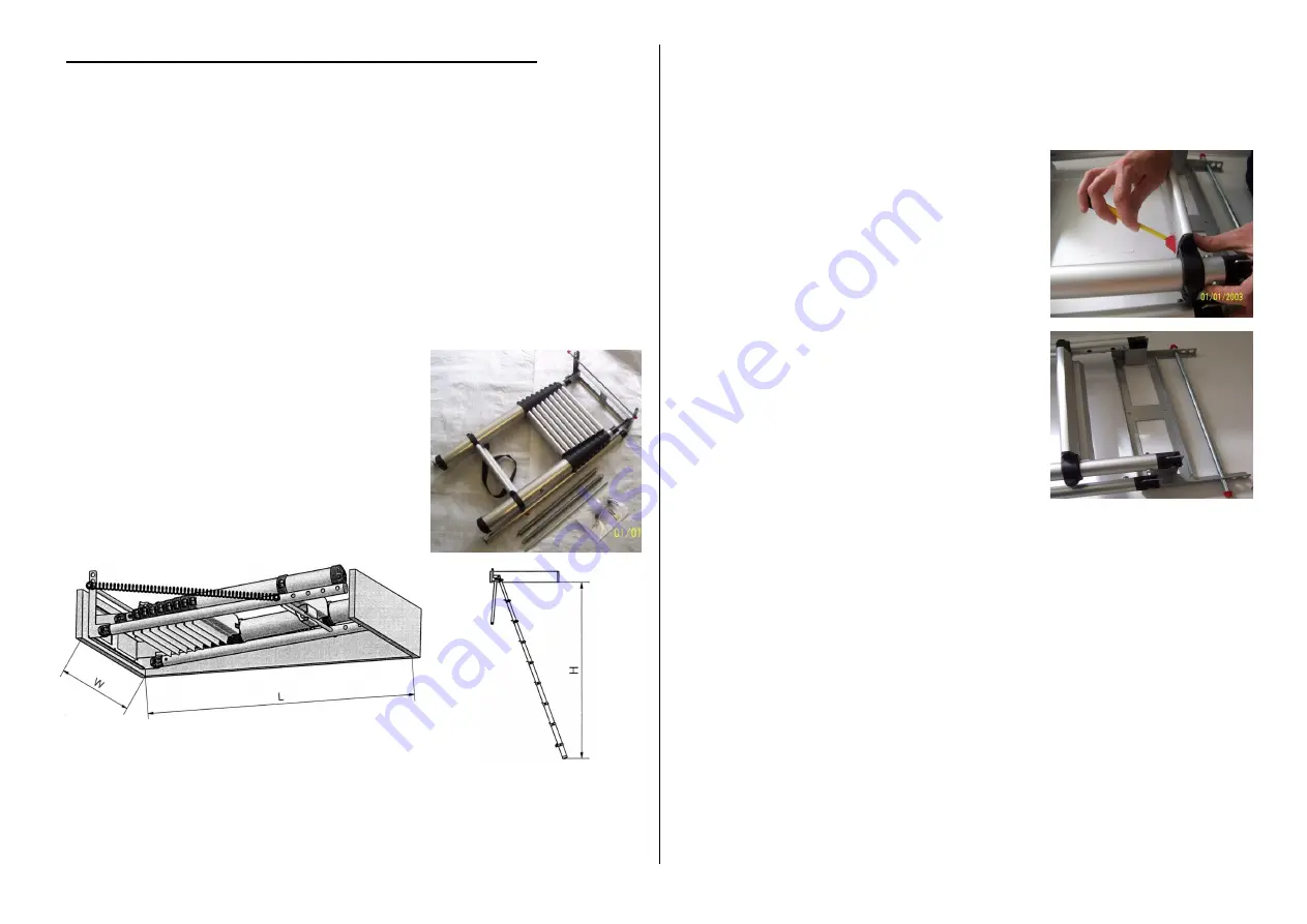
The loft ladder model supplied comprises:
1x Ladder/sub frame assembly
2x springs
3x Carrier/strap, spring rods.
Adjustment instructions
Prior to fitting, measure and make note of the floor to ceiling height where you
will be installing your loft ladder. Use table 1 (overleaf) to identify the
configuration that is required for your floor to ceiling height and ensure you
have sufficient clearance for the ladder to be installed in the loft hatch.
Please ensure that you only reference the column data for the model of ladder
purchase.
Once you have identified which configuration is required to suit your floor to
ceiling height, you may have to adjust the ladder length as follows:
1.
With the ladder/carriage assembly laying
flat (See Fig 2). Use the flat bladed
screwdriver to lever the inside edge of the
first top rung locking lever while applying a
small amount of pressure on the top of the
rung towards the bottom of the ladder (See
Fig 2) this will disengage the first lock.
2.
Repeat step 1 for the second locking lever
on the top rung. This will then allow you to
slowly slide the rung down the stile tubes to
the second set of holes where the locking
levers will automatically lock into position.
3.
Simply repeat steps 1 and 2 until you have
the correct number of holes visible above
each rung end as required for your
configuration. Once you have the ladder
configured correctly ensure that both levers
are fully engaged (flush with underside of the rung) and the top tubes are
equal in length (See Fig3).
The ladder can now be fitted into position by following the standard instructions
supplied with the ladder. Once fitted, locate the first spring rod in the correct
position on the ladder fixing bracket for your configuration.
Fit the second spring rod through the first set of holes (on the bracket side) in
the two tubes which make up the sub frame. Please note that whichever
configuration is required this spring rod is always kept in this position on all
models.
The third rod must be positioned correctly through both sets of holes on the sub
frame tubes for your configuration; this is the rod that the ladder hook locates
onto when the ladder is closed.
Note: If ladder adjustment is not required, the closed ladder hooks over the
same bar that the springs are fitted to. In this instance the third bar is not
required.
Fig 1
Fig 2
Fig 3


