background image


REGULATED DC POWER SUPPLY 


• 

PS1210 12V 1A 

• 

PS1220 12V 2A 

• 

PS1230 12V 3A 


INSTALLER’S MANUAL 


WARNING 

This manual contains information on limitations regarding product use and function and information on the 
limitations as to liability of the manufacturer. The entire manual should be carefully read. 


All specifications are subject to change without notice.


- 1 - 

Summary of Contents for PS1210 12V 1A

Page 1: ...LER S MANUAL WARNING This manual contains information on limitations regarding product use and function and information on the limitations as to liability of the manufacturer The entire manual should be carefully read All specifications are subject to change without notice 1 ...

Page 2: ...of installed products Damages caused by failure to use the product for its normal purpose Damages caused by improper maintenance Damages resulting from any other cause bad maintenance or product misuse In the case of a reasonable number of unsuccessful attempts to repair the product covered by this guarantee the manufacturer s liability shall be limited to the replacement of the product as the sol...

Page 3: ... 3 Contents 1 PURPOSE 4 2 STANDARDS 4 3 TECHNICAL SPECIFICATIONS 4 4 INSTALLATION 5 5 CONNECTION SCHEME 7 6 TROUBLESHOOTING 8 ...

Page 4: ... 6 Electronic protection against short circuit at output 3 7 Single LED display on cover Color of display Green basic power supply is on battery charged Orange basic power supply is on no or low level battery charge Red basic power supply is off and low level battery charge No display basic power supply is off battery charged No display basic power supply is off no backup power supply 3 8 Output m...

Page 5: ...rom heat and humidity Cut out the profile board 1 Drill through the marked places 2 1 2 Undo the two screws 1 Turn off the LED prior to removing the cover 2 3 Mount the box on the middle screw placed in advance 1 and do the remaining four screws 2 5 ...

Page 6: ... outputs may also be used I for mains supply availability and F for battery discharge Mount and connect the battery 6 Turn on the LED cable 7 The LED will light in red for Ubatt 10 5V Turn on the mains 9 The LED should light in green Should it light in orange leave the battery to charge for at least one hour Where necessary adjust Uout using the trimmer potentiometer 4 5 Place the cover 1 back and...

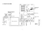
Page 7: ...5 CONNECTION SCHEME 7 ...

Page 8: ...battery to charge and check it again in about 15 minutes 2 Maximum output current has been exceeded 1A for PS1210 2А for PS1220 3А for PS1230 Check the consumed charging current If it is greater than the reference there could be a fault in any of the powered modules or devices 3 If the voltage remains low despite the low level of the current consumed the device must be dismantled and taken to the ...

Reviews: