background image


Color


Touch


Screen


Installation


Guide


Teletrac, Inc                                                          1557-0300 00 

Page 3 


ƒ


DO


NOT


use


the


existing


factory


wires


attached


for


grounding.


This


may


cause


interference.


o


Run


Ignition


Wire

 ‐ 

Attach


one


end


of


the


fuse


holder


to


determine


a


+12


volt


(using


a


Multi

meter)


ignition


switch


source


that


will


be


set


as


ground.


ƒ


Recommend


to


have


it


places


behind


the


ignition


cylinder,


fuse


box


or


the


starter


solenoid


in


the


engine


compartment.


**TIP:


Use


a


voltmeter


to


make


sure


the


voltage


of


the


attached


line


DOES


NOT


get


dropped


to


zero


while


the


engine


is


starting


(Cranking).


This


line


will


be


referred


as


the


“True


Ignition”.


5.


Mount


the


TM2/TM2J


to


vehicle’s


chassis


with


mounting


bracket.


6.


Secure


the


unit


with


four


screws


or


four


cable


ties.


7.


Zip

tie


any


excess


wire


slack


around


the


fuse


holder


to


prevent


tampering.


8.


Attach


Prism


wiring


harness


to


the


Prism


TM2/TM2J.


9.


Verify


all


wires


are


soldered


or


crimped

.


10.


Connect


the


GPRS


and


GPS


connectors


to


the


Prism


TM2/TM2J.


11.


Attach


the


main


power


and


insert


the


fuse


you


removed


in


step


#5.


12.


Confirm


the


unit


receives


GPS


and


GPRS


signals.


13.


Turn


the


vehicle


key


to


the


ON


position


and


verify


the


CTO


is


active.


14.


Properly


secure


the


CTO


by


using


the


supplied


double

‐ 

side


tape.


15.


Secure


the


bracket


with


screws.


*


Be


sure


to


have


customer


approval


before


securing


the


bracket


with


screws.


CABLE


AND


FUNCTION


It


is


important


to


determine


if


the


CTO


will


be


“Messaging


Enabled”.


If


the


CTO


will


be


used


as


a


message


display


terminal


(MDT)


you


must


use


the


correct


cable.


The


messaging


cable


will


be


tagged


indicating


it


is


“message


ready”.


If


messaging


will


not


be


used,


please


use


the


cable


without


a


tag.


WIRING


FOR


A


CTO


Because


the


CTO


has


its


own


power


connector


in


order


to


facilitate


its


wiring,


the


following


steps


are


to


be


followed;


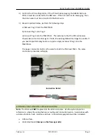
1)


Install


the


TM2/TM2J


as


normal,


ensuring


that


all


the


rules


are


followed


and


make


sure


that


the


TM2/TM2J


comes


on


and


it


registers


with


the


network.


2)


Disconnect


the


6


pin


power


plug


from


the


TM2/TM2J


and


connect


it


into


the


3


pin


female


plug


coming


from


the


CTO


pig


tail


loom.


Make


sure


that


the


lock


of


the


6


pin


power


Molex


locks


onto


the


tab


of


the


3


socket.


3)


Connect


the


6


pin


side


of


the


pigtail


from


the


CTO


into


the


TM2/TM2J.


See


the


following


pictures.


Summary of Contents for Color Touch Screen

Page 1: ...Color Touch Screen Installation Guide for the Prism TM2 and TM2J Units Document Number 1557 0300 00 Date June 29 2009...

Page 2: ...ration Installation Form 1 Installation Instructions 2 Cable and Function 3 Wiring for a CTO 3 Suitable Locations for Prism Mounting 4 Suitable Locations for the CTO 5 CTO Mount 5 Steel Bracket 5 Inst...

Page 3: ...mount or a combo glass mount antenna Wiring harness Standard TM2 TM2J harness with 8 pin connector or VLU to Prism adapter PRE INSTALLATION VEHICLE INSPECTION Ensure that all major electrical and mec...

Page 4: ...G it 2 If a WEDGE antenna is used be sure to place it on the passenger side of the windshield 3 If a Roof Mounted antenna is used the installation requires a hole be drilled on the vehicle o Note The...

Page 5: ...ved in step 5 12 Confirm the unit receives GPS and GPRS signals 13 Turn the vehicle key to the ON position and verify the CTO is active 14 Properly secure the CTO by using the supplied double side tap...

Page 6: ...TO will receive Power Ground and control signal Note the existing DB9 will no longer be usable if you need to perform diagnostics or repairs simply reconnect Plug 1 into the TM2 TM2J The power connect...

Page 7: ...of MDTs will apply for the CTO Place the CTO within easy reach of the driver Avoid the top of the dashboard It is illegal in some states and if any holes are drilled they can not be easily repaired A...

Page 8: ...INSTALLING THE BRACKET TO THE CTO Remove the bottom screws of the CTO mount to gain access to the silver Phillips screw inside the mount Remove and replace it with the Steel Bracket utilizing the lon...

Page 9: ...reprogramming the SD card be sure to place a new sticker before leaving the vehicle The stickers are available through Distribution and do not have a part number Simply order the labels as part of th...

Reviews: