Color
Touch
Screen
Installation
Guide
Teletrac, Inc 1557-0300 00
Page 4
4)
Confirm
the
CTO
configuration.
It
the
CTO
will
do
messaging
the
GREEN
Cable
on
PLUG
3
must
be
connected
to
the
RED
wire.
If
the
CTO
will
not
do
messaging,
then
the
Green
wire
must
be
connected
to
the
BLUE
wire.
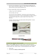
5)
Based
on
picture
below,
perform
the
following
steps:
a)
Remove
Plug
1
from
the
TM2/TM2J.
b)
Connect
Plug
1
into
Plug
2.
c)
Connect
Plug
3
into
the
TM2/TM2J.
This
will
ensure
that
the
CTO
will
receive
Power/
Ground
and
control
signal.
Note;
the
existing
DB9
will
no
longer
be
usable,
if
you
need
to
perform
diagnostics
or
repairs
simply
reconnect
Plug
1
into
the
TM2/TM2J.
The
power
connector
(6
‐
Pin)
is
the
same
for
both
the
TM2
and
TM2J.
The
same
connection
procedure
will
apply.
Connection
Detail
SUITABLE
LOCATIONS
FOR
PRISM
MOUNTING
Note
:
The
Prism
will
NOT
be
placed
on
the
driver
side
area.
Use
the
system
layout
as
reference
to
where
the
wiring
harnesses
routing
and
connection
points.
Avoid
places
with
extreme
vibration,
heat,
moisture
and
dust.
All
installed
equipments
will
be
concealed.
•
A
flat
surface.
•
Under
dashboard
(
Always
on
the
Passenger
side
).

