INSTRUMENT MANUAL
VACUUM GAUGE MODEL MM200
160Phone:(215) 947-2500 fax:(215) 947-7464 e-mail:sales@televac.com web site:www.televac.com
MM-200_im REV M
Page 30 of 160
TELEVAC
THERMOCOUPLE MODULE
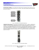
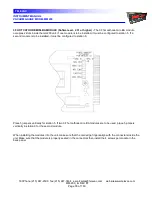
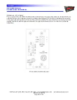
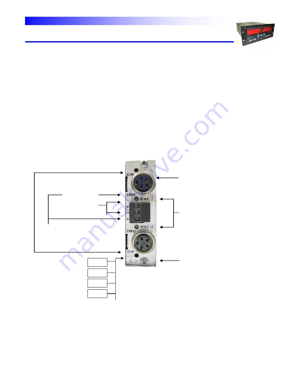
- The rear panel of the thermocouple module is shown in Fig. 3.7. The gauge tube
cables can be connected by inserting the cable connector into the socket and turning the shell clockwise to engage
the screw threads for retention of the connector.
The thermocouple module is designed to work with the type 2A thermocouple gauge tube. Special electronics have
been added to the 2A thermocouple module to allow the 2A gauge tube to operate up to 20 Torr (20,000 microns).
An analog "0-10V" output (normally 0 to 10VDC) is available at the connector in the center of the panel. This
output covers the range of 0 to 1000 microns only in order to give good definition to the data in this lower range.
Other outputs are also available. An optional 0 to 10 mVDC is also available (See Section 902). There are three
terminals available. The center terminal is a common ground and negative terminal for both the upper and lower
thermocouple stations. The upper and lower terminals are the positive signals for the upper and lower stations,
respectively.
Between the cable connector and the analog “0-10V” output terminal is a "zero" potentiometer for the thermocouple
gauge tube. This potentiometer is used, if required, to adjust the current to the thermocouple sensor "heater",
which can be used to compensate, over a limited range, for effects of contamination from the process in the
vacuum chamber. The ATM adjust is not used for the thermocouple gauges.
Fig. 3.7 - Rear Panel of the Thermocouple, Convection and Diaphragm Modules
INSTALLATION SCREW
UPPER AND LOWER
SENSOR ID NUMBER
[FIVE] *
FOUR PIN
CONNECTOR
(FEMALE)
SPAN OR
ATMOSPHERE ADJUST
(DIAPHRAGM, CONVECTION, CDG)*
ZERO ADJUST
0-10V OUTPUT
DI 1E
TC 2A
CV 4A
CDG
XXX

