INSTRUMENT MANUAL
VACUUM GAUGE MODEL MM200
160Phone:(215) 947-2500 fax:(215) 947-7464 e-mail:sales@televac.com web site:www.televac.com
MM-200_im REV M
Page 40 of 160
TELEVAC
400 OPERATION
Turn the power switch, located on the rear panel, to the ON position. If the gauge is installed in a rack or cabinet
where the power switch is not accessible, power may be left on without damage to the instrument.
401 DISPLAY DESCRIPTION AND DEFINITIONS
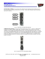
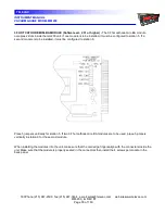
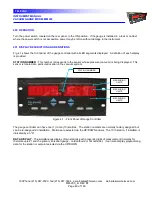
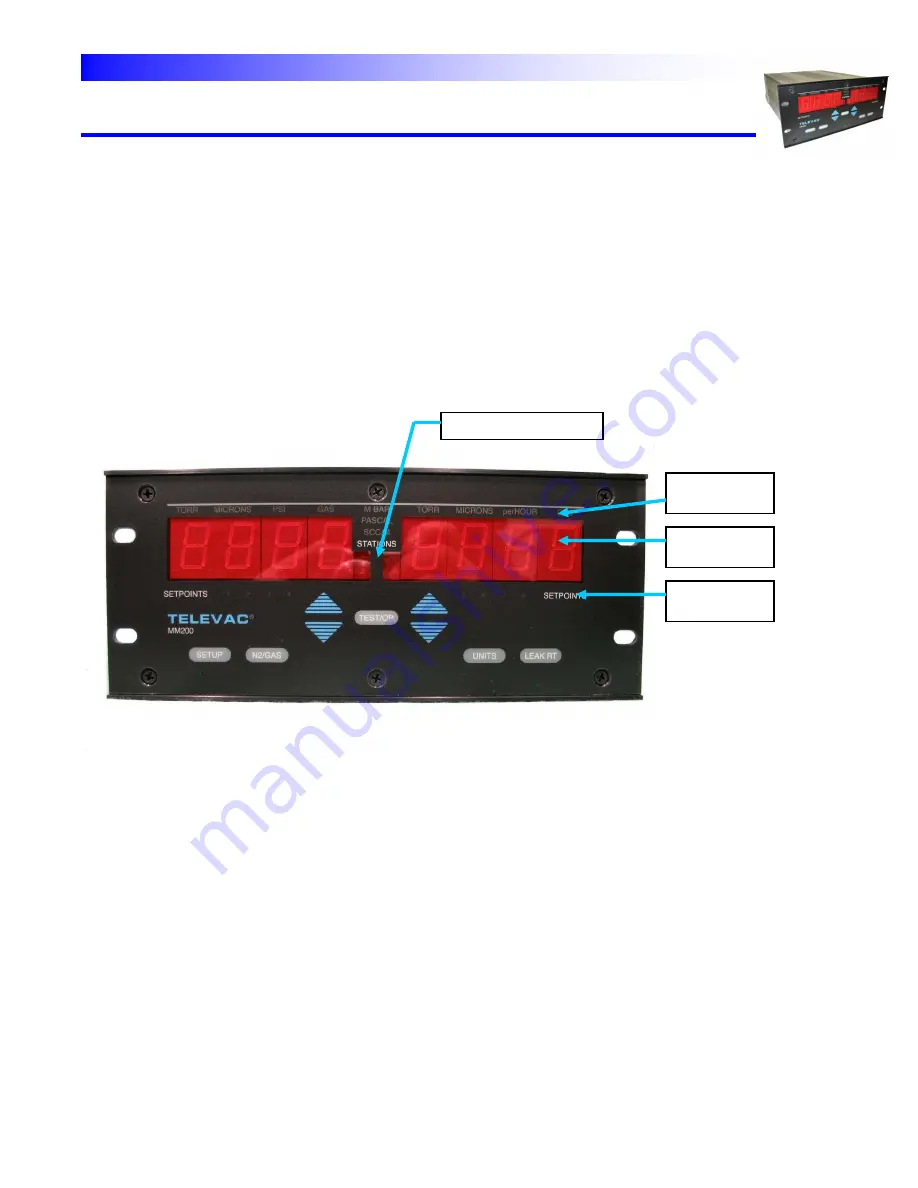
Fig. 4.1 shows the front panel of the gauge controller with all LED segments displayed. A definition of each display
is provided.
STATION NUMBER
- This number corresponds to the sensor whose pressure (vacuum) is being displayed. This
sensor is located at a particular location in the vacuum system.
Figure 4.1 - Front Panel of Gauge Controller
The gauge controller can have one (1) to ten (10) stations. The station numbers are normally factory assigned but
can be re-assigned at installation. Stations are selected via the UP/DOWN arrows. The 10 th station, if installed, is
indicated by an "A".
DATA DISPLAY
- The simultaneous display of two stations each present 4 digits of measurement (normally for
thermocouple #1 and the primary ionization gauge - cold cathode or hot cathode). It can also display programming
data for the station or setpoint selected via the UP/DOWN
STATION NUMBER
MEASURING
UNITS
MEASURING
UNITS
MEASURING
UNITS

