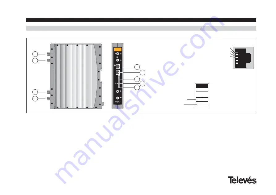
4. - ELEMENT DESCRIPTION
4.1.- SAT-RF
1
2
3
4
234756
PRGM
PWR
A/V
SAT-RF
5
6
7
8
9
1.- IF input + V
LNB
/ 22KHz
2.- IF output
3.- RF input
4.- RF output
5.- A/V output (1)
6.- Programmer connector
7.- Module powering input
8.- LED
9.- Control Bus connector
The SAT-RF transmodulator turns a TV or
radio channel (selected by the user) from the
existing channels in a satellite transponder
(FM analogue modulation and an approxi-
mate bandwidth of 27 MHz) into a VHF/UHF
channel (PAL / SECAM standard modulation
and a bandwidth of 7/8 MHz).
The selection of the different parameters
(input frequency, audio subcarrier, output
level, output frequency, ...) is carried out
using the programmer ref. 7234, that is con-
nected to the front of the device.
The SAT-RF transmodulator disposes of an
IF input and output in the upper “F” connec-
tors with the aim of enabling the input signal
to pass to various modules, it also allows
the powering of a converter via the IF input
(13V or 18V), as well as being able to gene-
rate a 22 KHz tone for the selection of the
converter's oscillator by this connector.
It also has an RF input and output connector
so as to be able to mix the channels for their
subsequent amplification.
-
-
-
-
-
-
-
-
(1)
Mass -1
Video output -2
“R” audio output -3
“L” audio output -4
-5
-6
-7
-8
Product reference
Indicates the programmed
output channel
SAT-RF
7310
Ch
24
User manual
SAT-RF


