9
User manual
TDT +
ENGLISH
4. - ELEMENT DESCRIPTION
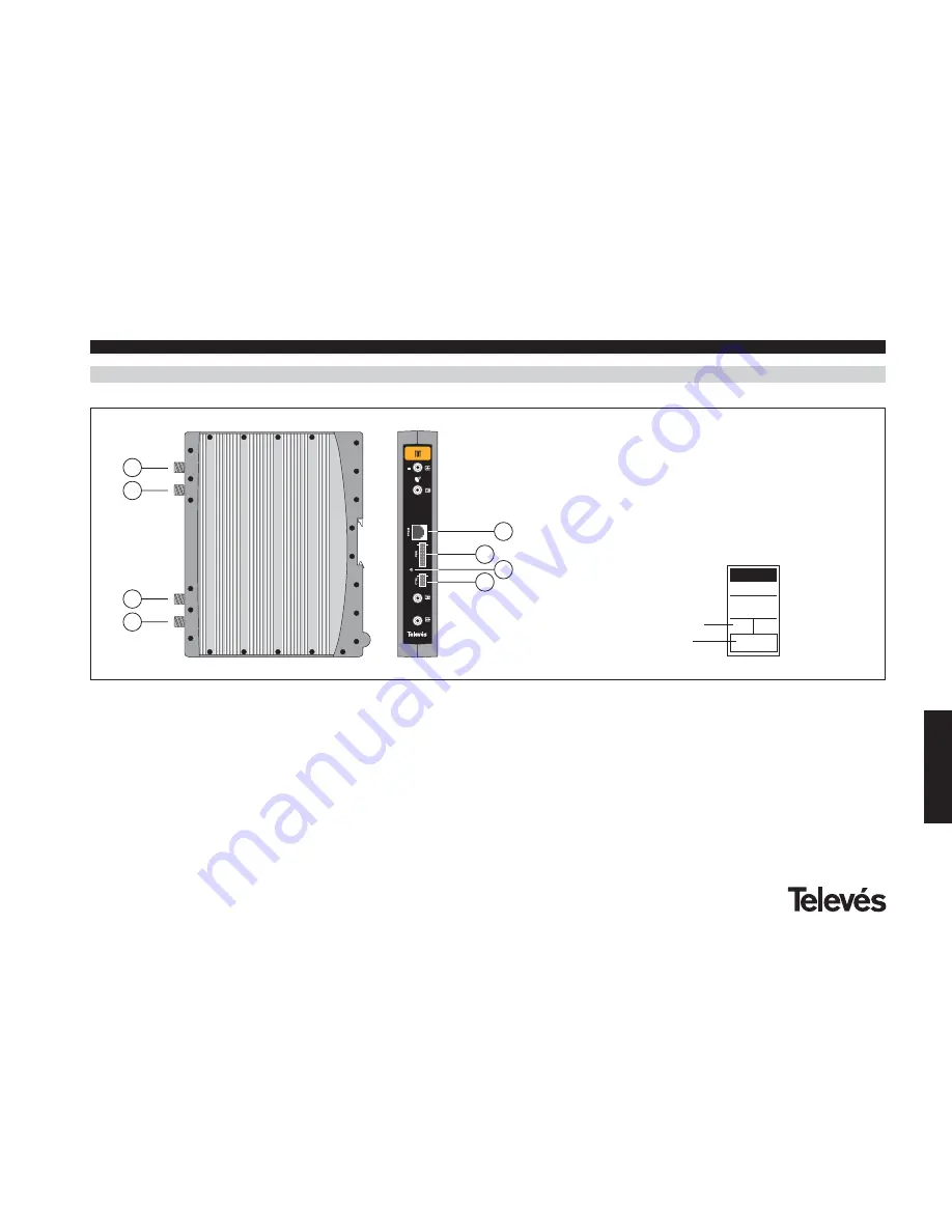
4.1.- TDT +
1
2
3
4
5
6
8
7
+
The transparent digital transmodulator,
referred to as the TDT+, turns the
information contained in a satellite
transponder for example (QPSK modulation)
and a maximum bandwidth of 36 MHz into a
VHF or UHF channel (QAM modulation) and
a maximum bandwidth of 8MHz (depending
on the selected QAM modulation).
The TDT+ performs the QPSK demodulation
of the input channel (transponder) obtaining
a MPEG2-TS signal (MPEG2 Transport
Stream). Then the TDT+ performs a QAM
modulation of this MPEG2 signal, which
implies a modulation change of the digital
information (digital transmodulation).
The input channel, the input signal
parameters and the output channel
paramters are selected using the
programmer ref. 7234 which is connected to
the front of the device.
It is also possible to control the unit using a
PC as explained in section 7.
The TDT+ disposes of an IF input and
output in the upper F connectors so as to
enable the input of the signal into various
TDTs +. It also allows us to power a
converter via the signal input (13/18 V).
In
the case of a shortcircuit, the front LED
flashes on and off, stopping when the
shortcircuit is over and when the 13/18V
is back in the connector
. It also has an
input and output RF connector, for the
channels to be mixed before they are
amplified.
1.- Satellite IF input
2.- Satellite IF output
3.- RF input
4.- RF output
5.- Programmer / PC connector
6.- Powering input
7.- LED
8.- Control BUS connector / +24V
Product reference
Indicate the programmer
output channel
TDT
5023
Ch


