background image

Summary of Contents for TPC I SYSTEM

Page 1: ......

Page 2: ...eo Systems Inc to notify any person of such revision or changes Warning This equipment generates uses and can radiate radio frequency energy and if not installed and used in accordance with the instru...

Page 3: ......

Page 4: ...by TeleVideo only the warranty if any given by the manufacturer thereof applies EXCLUSIONS This limited warranty does not cover losses or damage which occur in shipment to or from Buyer or Customer o...

Page 5: ......

Page 6: ...Reset Command 3 4 System Prompt and the Logged Drive 3 4 CP M Command Lines 3 5 Upper and Lower Case 3 5 Control Characters 3 5 Line Editing 3 5 Disk Files 3 6 Filenames 3 7 Wildcard File References...

Page 7: ...ntrol 6 7 Cursor Addressing 6 8 Tabs 6 10 Text Editing Functions 6 10 Monitor Mode 6 12 7 Video Graphics 7 1 8 Introduction to GSX 7 1 GSX Graphics System EXtensiQn 7 1 Graphic Device Operating System...

Page 8: ...E F G H Cable Specifications Port Addresses Communications Port Driver Changing the Default LST Device Default Device Assignment D 7 E 8 F 15 G 20 H 24 I ASCII Code Chart I 26 J System Diskette File...

Page 9: ......

Page 10: ...splay is 24 lines by 80 characters The graphics display features a resolution of 640 x 240 pixels Figure 1 1 TPC I The slim line 5 1 4 inch floppy disk drives are mounted vertically and side by side n...

Page 11: ...designed to run under CP M Some of the more popular languages that are used on the TPC I are BASIC FORTRAN COBOL PASCAL APL ALGOL PL l FORTH and C Besides TeleCalc TeleChart and TeleWrite there are ma...

Page 12: ...u will see it as Ctrl C Do not press the slash key when you see it in a command Press the slash key ONLY when it is enclosed in brackets like this I Special Notes Two types of notes call attention to...

Page 13: ......

Page 14: ...feet from other computing equipment electrical appliances or equipment such as elevators radio transmitters and television sets that generate magnetic fields Power Cord Connection The power cord tha...

Page 15: ...ettings control many system functions Most switches can be set according to your preference but others must be set in required positions During installation it is important that you check the switch s...

Page 16: ...fault settings Table 2 1 Switch Settings Setting set to up or Section down Function 1 closed down Baud rate see Table 2 2 2 closed down Baud rate see Table 2 2 3 closed down Baud rate see Table 2 2 4...

Page 17: ...bilities of the SETUPTPC Program as well as step by step instructions for using it are in Chapter 5 NOTE If you are adding a plotter or the SuperMouse please follow the installation instructions that...

Page 18: ...within 50 feet of each other Attach the end of the interface cable with the 25 pin D shaped connector to the port labeled PRINTER Attach the other end to the 36 pin connector on the printer See Appen...

Page 19: ...Modem Baud Rate Switch Settings Dip Switch Section 1 2 3 Baud Rate c c C 9 600 0 C C 4 800 C 0 C 2 400 o 0 C 1 200 C C 0 600 o C 0 300 COO 150 000 75 Legend C Switch closed down o Switch open up TeleV...

Page 20: ...supervises their execution It organizes the data for communications to a printer or over a modem to a remote station One way to think of CP M is as the personality that resides in your computer it is...

Page 21: ...and this is the drive that CP M searches to load the command A collection of programs that gives instructions to the computer for the execution of applications programs on a computer The kernel of CP...

Page 22: ...ps for starting your system and activating the operating system The following is a quick review of those steps as they relate to CP M System Diskette In the User s Manual you learned how to set up you...

Page 23: ...ors after you turn on the power If you still have problems run through the installation procedure in Chapter 2 a few times and check the Troubleshooting section in Chapter 8 If the problem persists co...

Page 24: ...lower case so that you can distinguish your entries from CP M responses on the screen When you name a file with lower case letters the name is displayed in upper case letters in the diskette director...

Page 25: ...ters on command line AS After a file or a list starts to display on the screen AS starts or stops toggles the scrolling of the display AU Cancel current command line positions cursor under command lin...

Page 26: ...s an extension of the filename and is useful for identifying different types of files in the disk directory Table 3 3 lists some common filetype extensions Table 3 3 Common Filetype Extensions Extensi...

Page 27: ...dcard for single and multiple character substitutions A era BAR d Return erases all files on the logged drive that begin with dO followed by up to three characters It also erases files that begin with...

Page 28: ...supplying a file specification with or without wildcard characters ERA Erase a File The ERA command erases the file or files specified A era BAR x filename ext Return In the special case of erase all...

Page 29: ...dynamic debugging monitor DDT and a file printing routine called DUMP You can see a list of the transient commands that carne on your CP M system diskette by typing A DIR BAR COM Return The filetype e...

Page 30: ...er This is often more useful than the DIR all on a line listing In addition to the sorted listing STAT displays other useful information about each file The STAT listing looks like this Recs Bytes Ext...

Page 31: ...B You may or may not want to ERAse the old copy disk space is a premium so developing good housekeeping practices can help you get the most out of your system Donlt wait for a disk full error message...

Page 32: ...cessing accounting financial analysis business graphics program development entertainment Included with the TPC I are three applications programs TeleWrite for executive word processing TeleCalc for s...

Page 33: ......

Page 34: ...pad perform one function when the Num Lock key is pressed and another function when the Num Lock key is pressed again The Num Lock key acts as a toggle switch changing the keys on the numeric keypad f...

Page 35: ...characters on the screen that do not seem to make any sense Figure 4 2 Function Keys and Special Keys Function Keys and Special Keys Table 4 1 summarizes the function of the special keys which are hig...

Page 36: ...numerics and vice versa without affecting the running program Generates 32 normally nondisplayed ASCII control codes when used with another key The control key combinations are used for special action...

Page 37: ...the computer NOTE The computer features an auto wraparound function that eliminates the need to manually enter an Return and a linefeed LF at the end of each aO character line The left arrow key on th...

Page 38: ...on of the next line If the cursor is at the end of the screen it scrolls up the screen Pressing Ins alone or Shift I Ins or Caps Lock I Insert inserts a line consisting of spaces at the cursor positio...

Page 39: ...aces are loaded into the last line of the page If half intensity is on half intensity spaces replace the erased characters These keys are not supported on the TPC I PrtSc PgUp PgDn Scroll Lock Break D...

Page 40: ...multaneously which become FII through F16 Using them in combination with Shift allows up to 32 sets of codes to be transmitted Programming the Function Keys When the t e r mina lis fir s t t urnedon t...

Page 41: ...on Key Values Key FI F2 F3 F4 F5 F6 F7 Fa F9 FlO Unshifted 1 2 3 4 5 6 7 a 9 Shifted A B c D E p2 is the following value 1 Send to the computer Ctrl Unshifted G H I J K message can contain up to 63 by...

Page 42: ...Esc I The key number 1 for key Fl The value 1 for send to computer The entry is NOTE Shift I Esc I 1 1 TURN ON THE PRINTER Return y 1 Entering the message followed by Return enters a carriage return a...

Page 43: ......

Page 44: ...that has the resident commands to another diskette FORMAT Formats a blank diskette for use on the TPC I The directions are divided into two parts a section for the single drive TPC and a section for a...

Page 45: ...ult I O BYTE The default I O BYTE may be changed to select anyone of the four physical devices associated with logical devices 2 Configuring the modem port The modem port can be conf igured to be used...

Page 46: ...TeleVideo Systems Inc Current system TPC I Operating system Stand alone CP M Current Mouse status OFF Select modification category 1 To attach mouse 2 To detach mouse 3 To change CP M default I O byte...

Page 47: ...rent BAUD rate and exit Enter appropriate number followed by RETURN or CTRL C to return to CP M Enter 4 Return if you wish to change baud rate to 1200 Displays SYSTEM SETUP Version x x TeleVideo Syste...

Page 48: ...rate 5 To change Modem port data format 6 To change Autoload file name 7 To save current configuration permanently and return to CP M 8 To save current configuration temporarily and return to CP M 9...

Page 49: ...iskette into the drive drive A if you have two drives 2 If the system prompt is not displayed reset the TPC I by pressing Ctrl Alt Del simultaneously If the system prompt is displayed go to step 4 3 4...

Page 50: ...program master diskette in drive B and enter B a Displays if you have one drive DESTINATION ON A THEN TYPE RETURN b Displays if you have two drives DESTINATION ON B THEN TYPE RETURN Press Return Disp...

Page 51: ...E ARE ERASED 1 Put the system diskette in the drive 2 If the system prompt is not displayed reset the TPC by pressing Ctrl Alt Del simultaneously or by turning the power off and on If the system promp...

Page 52: ...o the floppy drive 11 Press Return SYSTEM 12 Displays USER 13 SYSTEM 14 forrnat ting Listen for a clicking sound as the program formats the diskette Displays Formatting Completed Format another Insert...

Page 53: ...ED 1 Put the system diskette in drive A 2 Insert the diskette to be formatted into drive B 3 If the system prompt is not displayed reset the TPC by pressing Ctrl Alt Del simultaneously If the system p...

Page 54: ...to abort Enter B the drive indicating where the diskette to be formatted is Displays Insert a diskette into floppy disk drive B Press RETURN when ready ESC to bort Press Return Displays forrnat ting...

Page 55: ...ng them If you do not know how to format a new diskette refer to the utility program FORMAT 1 Insert the system diskette into the drive 2 If the system prompt is not displayed reset the TPC by pressin...

Page 56: ...a clicking sound as the program copies the diskette SYSTEM 13 Displays alternately several times while copying USER Insert MASTER diskette in the drive Press RETURN when ready Insert DESTINATION disk...

Page 57: ...ary use a new formatted diskette 3 Try copying another diskette 4 Run the program using another system diskette COPYDISK DUAL DRIVE COPYDISK copies the contents of one floppy diskette onto another flo...

Page 58: ...eo Systems Inc xxK CP M version y y double drive A Enter COPYDISK Return Displays COPYDISK TS 803 TS 803H TPC I Vx x c 1983 TeleVideo Systems Inc Source Drive ESC to abort Enter A Either drive can be...

Page 59: ...in the correct drives NOTE 14 Press Return If you entered incorrect drive names for the source drive and destination drive press the space bar to re enter the correct dr i vee SYSTEM 15 Displays USER...

Page 60: ...the suggestions listed below utility Programs 1 Run COPYDISK again reversing the source and destination drive designations 2 Make sure that the diskette used as the destination is not defective or da...

Page 61: ......

Page 62: ...anies the applications programs they want to run on the TPC I SUBSYSTEMS OVERVIEW The TPC I video display can be described as comprising several basic subsystems CPU Terminal Emulator Graphics Driver...

Page 63: ...AL EMULATOR The CPU is a ZILOG Z80A operating at 4 MHz The system has three different kinds of memory an 8K EPROM containing the system boot diagnostics and display control a 32K block of video displa...

Page 64: ...he control logic switches to the full 64K RAM memory configuration and the software initializes the lower RAM system scratch space The EPROM then serves as a video display graphics driver When special...

Page 65: ...e 6 1 Video Attributes Attribute Normal Video Reverse Video Underline Blink Invisible Description Restores the background of the screen to that selected by rear switch settings Changes the background...

Page 66: ...only for the sake of clarity and are not to be included in the sequence Escape Sequence Calls to the Terminal Emulator The Terminal Emulator is a gate array processor that intercepts escape sequences...

Page 67: ...G 0 ESC G I ESC G 2 ESC G 3 ESC G 4 ESC G 5 ESC G 6 ESC G 7 ESC G 8 ESC G 9 ESC G ESC G I ESC G ESC G ESC G ESC G ESC ESC The clear function is used to clear data from screen memory Clear commands ar...

Page 68: ...control commands in Table 6 5 or by sending the cursor to a screen address as described in the section on Cursor Addressing in this chapter Table 6 5 Cursor Control Commands Cursor Control Up Down Le...

Page 69: ...scrolls down one line when the cursor reaches the top line of the screen As the display scrolls down one line a new line of data appears at line one of the screen and the last line of the display is...

Page 70: ...lumn Transmitted 1 Space 33 65 2 1 34 A 66 a 3 n 35 B 67 b 4 36 C 68 c 5 37 D 69 d 6 38 E 70 e 7 39 F 71 f 8 40 G 72 g 9 41 H 73 h 10 42 I 74 i 11 43 J 75 j 12 44 K 76 k 13 45 L 77 1 14 46 M 78 m 15 4...

Page 71: ...line Clears the tab where the cursor is located when this code is entered Clears all tabs regardless of the position of the cursor when the code is entered To set a tab move the cursor to the column...

Page 72: ...t one position At the end of the delete function a space is written into the last position on the line If half intensity is on half intensity spaces replace the erased characters ESC E Inserts a line...

Page 73: ...e page and replaces them with null characters If half intensity is on half intensity nulls replace the erased characters You can display all characters including all escape and control sequences sent...

Page 74: ...4 E T E ENQ 05 E Q F ACK 06 A K G BEL 07 B L H BS 08 B S I HT 09 H T J LF OA L F K VT OB V T L FF OC F F M CR OD C R N SO OE S 0 0 SI OF S I p DLE 10 D L Q DCl 11 D 1 R DC2 12 D 2 s DC3 13 D 3 T DC4 1...

Page 75: ...em Reference Manual ProgralDIning A V SYN 16 S Y AW ETB 17 E B AX CAN 18 C N Ay EM 19 E M A Z SUB lA S B A ESC IB E C A FS lC F S A GS 10 G S AA RS IE R S A US IF U S DEL DEL 7F TeleVideo Systems Inc...

Page 76: ...es you with information about how a graphics system is built when using GSX It is intended for those who want to familiarize themselves with the basic capabilities of GSX For more specific information...

Page 77: ...s Your applications program accesses GOOS through a mechanism analogous to the normal BOOS systems calls GDOS loads at runtime with your graphics applications program so it consumes system memory spac...

Page 78: ...eVideo for the TPC I TS 803 TS 8038 TS 1603 and TS 1602 is supplied in this chapter Some manufacturers of graphics devices supply drivers for their devices GENGRAF Utility The GENGRAF utility is used...

Page 79: ...The resulting MYFILE COM file would be ready to run You should be aware of the total memory space available to your applications program in the TPA This will be less for graphics applications than fo...

Page 80: ...IDS MicroPrism 480 IDS Prism 80 132 monochrome IDS Prism 80 132 color Okidata Microline 92 Printronix MPV Printronix P300 P600 Plotters Hewlett Packard 7470A Hewlett Packard 7220 Houston Instruments H...

Page 81: ...X x Y coordinates in unit of pixel The TPC I is also equipped with an optical SuperMouse interface The SuperMouse has eight software support functions which are described in the SuperMouse Support Fu...

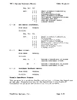
Page 82: ...n the section of this chapter called Sample Graphics Access Program Using 8080 Assembly Code Suggestion it is very useful to create a macro for access to the graphics output primitives grout macro RST...

Page 83: ...C 13 HL l C 14 HL 1 HL OFFOOh HL 5 HL clear graphic display set character color to 1 set writing mode to replace get pointer to string array put length of string into array HL point at string DE strin...

Page 84: ...unctions They are listed by function identification number passed in register C in Table 7 1 Table 7 1 Graphics Driver Functions Function Number Parameters 0 C 0 1 C 1 2 C 2 3 C 3 array TeleVideo Syst...

Page 85: ...4 y2 yl y2 word 5 x3 line to vertex x3 y3 word 6 y3 etc MoveTo Updates the current position Used only with LineTo and DrawString LineTo Draws a line from current position to x y then updates the curr...

Page 86: ...8 bit by a bit character cell The graphics character string starts at the character cell s baseline at the current X Y position The current position can be changed by the MOVETO command BASELINE 7 Sc...

Page 87: ...ing out the horizontal sections of a polygon or bar fill NOTE X2 must be g rea ter than or equal to Xl Crosshair This function can be used to draw a cross hair cursor of size specified by the user Thi...

Page 88: ...Value of vertical line of cross hair I 1 I IYI Value of bottom endpoint of vertical line I 1 I IY2 Value of top endpoint of vertical line I Crosshair Cursor X Y2 I I I I XI Y X2 Y I I I I X YI Word W...

Page 89: ...RESERVED 11 C 11 HL style 12 C 12 HL color 13 C 13 HL color TeleVideo Systems Inc RESERVED Set LineStyle Valid parameters are 1 through 8 1 solid 2 dashed 3 dotted 4 dash dot 5 long dash 6 short dash...

Page 90: ...hen NOT Writing Mode Logic 1 Plane Color Index AND Pattern 2 Plane Plane OR Color Index AND Pattern 3 Plane Plane XOR Color Index AND Pattern 4 Plane Plane AND Color Index AND Pattern 5 Plane Color In...

Page 91: ...Fill Interior Styles Style I o 1 2 3 Style Hollow Solid Pattern Cross hatch Fill Style Index This routine sets the style index of the currently selected interior style The style index only affects th...

Page 92: ...with the most significant bit corresponding to the lower x value The bytes are loaded into the array in order of increasing x from left to right on the scan line The TPC I provides eight SuperMouse su...

Page 93: ...uction set RST 30h for the Z80 instruction set The eight SuperMouse support functions and six hardware graphics cursor support functions that you may access are listed in Table 7 4 Table 7 4 SuperMous...

Page 94: ...ted as a keyboard entry and that the SuperMouse stops tracking its movement until the key is released The ASCII character associated with the SuperMouse key can be altered through SuperMouse function...

Page 95: ...nate range of the SuperMouse INPUT This returns the SuperMouse coordinates to the user USER SYSTEM Enters nothing Returns Reg HL Reg DE Reg A 0 SuperMouse s current X coordinate position SuperMouse s...

Page 96: ...er per key depression 1 The tracking of movement by the SuperMouse continues even while the SuperMouse key is pressed The ASCII character associated with the SuperMouse key that is pressed is not plac...

Page 97: ...tion x 0 639 Y 0 239 Inquire cursor attributes and status To BIOS Nothing From BIOS Reg ACC LSB Bit 0 I 1 I 2 I 3 I 4 5 6 7 Small crosshair nonblinking supported Full screen crosshair nonblinking supp...

Page 98: ...y cursor Small crosshair nonblinking Full screen crosshair nonblinking Small crosshair blinking Full screen crosshair blinking Currently not used Does not display cursor Display cursor Current X coord...

Page 99: ...through the SETUPTPC program on your diskette 6 Type MSCDRAW Return 7 Move the SuperMouse on its pad which in turn will doodle on the graphics screen EQU 0005H BOOS entry point ORG 100H MVI C 1 Initia...

Page 100: ...ters associated with each ASCII character The font is stored in the EPROM Each cell of the font can be individually accessed through the DRAWSTRING function Internally this is done as follows 1 The AS...

Page 101: ...ll Style Index 2 10 Fill Style Index 3 11 Fill StyleIndex4 12 Fill Style Index 5 13 Fill Style Index 6 14 Fill StyleIndex7 15 16 17 18 octagon 19 X 20 21 22 23 24 25 26 TeleVideo Systems Inc Half tone...

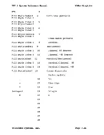
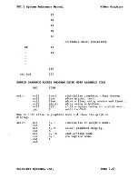
Page 102: ...t line plylin fill o initialize graphics clear screen draw graphic text draw a line using moveto and lineto draw using poly line fill a square using horizontal scan exit to CP M How to initialize to g...

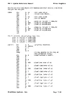
Page 103: ...the polyline function move to xl yl 100 120 line to x2 y2 150 150 line to x3 y3 200 120 line to x4 y4 250 150 plylin mvi c 3 polyline function lxi h OFFOOh mov e m inx h mov d m xchg hl now points to...

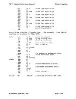
Page 104: ...ic text For example draw Hello starting at location x 400 y 120 text loop1 string mvi 1xi 1xi rst mvi lxi rst 1xi c 4 h 400 d 120 5 c 13 h 1 5 h OFFOOh mov e m inx h mov xchg mvi mov 1xi inx inx ldax...

Page 105: ...t cross hatch fill style 5 c 16 Set fill style index h OFFOOh e m h d m hl points at top of parameter table m 0 select vertical cross hatch style 5 c 17 Set fill color h OFFOOh e m h d m hl points to...

Page 106: ...TPC I System Reference Manual dcr jnz ret end b loop2 TeleVideo Systems Inc Video Graphics Ifill square from bottom to top Page 7 31...

Page 107: ......

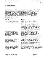
Page 108: ...TOR COMMAND TPC I IS USED WITH MODEM AND DOES NOT RESPOND OR TRANSMIT TO NETWORK PROCESSOR TeleVideo Systems Inc Action Unplug power cord and plug it in again Test for power by plugging something else...

Page 109: ...t printer cable being sure it is completely on the pin connector Check printer cable configuration Check for printer fault out of paper or ribbon Reset the system by turning the power off and on Re en...

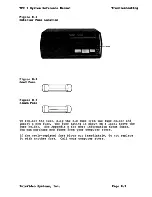
Page 110: ...p the old fuse from the fuse holder and insert a new fuse The fuse rating is shown on a label above the fuse holder See Appendix N for more information about fuses You can purchase new fuses from your...

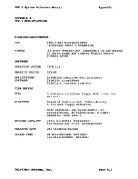
Page 111: ...Kbytes 32 Kbyte alpha and graphic display memory 8 Kbyte EPROM CP M 2 2 GSX 80 TeleWrite executive word processor TeleCalc spreadsheet TeleChart business graphics 5 1 4 inch slim line floppy disk driv...

Page 112: ...erial port 75 150 300 600 1200 2400 4800 9600 Word structure Eight data bits one stop bit RS 422 port 115 VAC 12 VAC 230 VAC 12 VAC 1 30 amp maximum at 115 VAC 0 65 amp maximum at 230 VAC NEMA standar...

Page 113: ...nderline 8 x 10 dot matrix 7 x 7 resolution 20 cps auto repeat Typeover Clear screen to space or null Character insert and character delete Line insert and line delete Absolute cursor addressing Erase...

Page 114: ...Berkeley CA 94710 A complete book for the beginning computer operator Covers all aspects of computer operation and CP M use Organization and presentation are outstanding 3 Zaks Rodney CP M Handbook K...

Page 115: ...O Box 579 Pacific Grove CA 95950 Published by Digital Research these references are available through your computer store from TeleVideo 8 Mostek for the STI chip 1215 W Crosby Rd Carrollton TX 75006...

Page 116: ...ara CA You should purchase the best quality diskettes available to ensure data integrity Diskettes are not that expensive to replace but the time spent getting data onto them is very expensive LIFE EX...

Page 117: ...ompliance with FCC regulations Figure D 1 RS 232C CONNECTOR HOUSING PIN 1 PIN 13 I o f SUB MINI 0 TYPE CONNECTOR 25 PIN MALE TeleVideo Systems Inc 10 CONDUCTOR CABLE 22 AWG ATLAS 200 22 10L BELDEN 845...

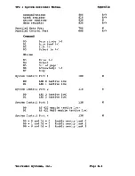
Page 118: ...cription Ready active high Motor on active low Hex Address OOH 20H 2FH 308 328 318 33H 408 42H 41H 43H 90H DO 01 02 D3 D4 D5 D6 D7 Side select active low Double density active low Drive select 0 activ...

Page 119: ...Busy System Control Port 1 DO Dl LED 0 active low LED 1 active low System Control Port 2 DO Dl LED 2 active low LED 3 active low System Control Port 3 80H 81H 82H 83H 70H 60H 10H IlH 12H DO Dl RS 422...

Page 120: ...of horizontal sync pulse Vertical total character number Vertical total adjust Vertical displayed character number Position of vertical sync pulse Mode control w w w w w w w w w BIT 3 0 for video dis...

Page 121: ...ard Board Connectors Appendix 1 P6 PS P4 P3 SWITCH 1 1 1 1 1 1 P7 1 P9 PI P2 P8 1___________________________________________________ The following tables describe the pin assignment of each connector...

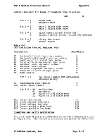
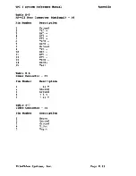
Page 122: ...14 15 Table E 6 Description Ground TXD RXD RTS CTS TXCK RXCK Ground TXD RXD RTS CTS TXCK RXCK Test Power Connector PI Pin Number 1 2 3 4 5 Table E 7 Description 12 V Unused Ground 5 V 12 V Video Conn...

Page 123: ...irection select Step Composite write data Write enable Track 0 write protected Composite read data Side select All the odd number pins are ground Table E 9 Keyboard Connector P3 Pin Number 1 2 3 4 5 6...

Page 124: ...ber Description 1 Strobe 2 Data bit o 3 Data bit 1 4 Data bit 2 5 Data bit 3 6 Data bit 4 7 Data bit 5 8 Data bit 6 9 Data bit 7 10 Acknowledge 11 Busy 12 Out of paper 13 Select 14 Auto feed 15 Error...

Page 125: ...ATUS REG TSR EQU 2EH TRANSMITTER STATUS REG UDR EQU 2FH USART DATA REGISTER COMMUNICATIONS PORT INITIALIZATION Application calls the routine at absolute address 0200H to initialize the communications...

Page 126: ...OUT PVR MVI A 80H OUT IDR MVI A O OUT TABCR LDA TADRD OUT TADR LDA TABD OUT TABCR LDA UCRD OUT UCR MVI A OIH OUT RSR MVI A 05H OUT TSR SUB A RET DB 0 DB 0 TeleVideo Systems Inc SAVE D AND E READ CURR...

Page 127: ...ress 02l0H to release communications port that is to restore it to its original condition This routine could be called immediately before applications returns to CP M COMRL RET GET COMMUNICATIONS PORT...

Page 128: ...zero if the UART is ready COMOS IN TSR ANI 80H RET iREAO STATUS REGISTER iLOOK ONLY AT RELEVANT STATUS BIT OUTPUT BYTE TO COMMUNICATIONS PORT Applications call the routine starting at absolute address...

Page 129: ...0290H whenever it wishes to determine carrier detect EIA PIN 8 status on the communications port On return register A is zero if carrier is not asserted non zero if carrier is asserted COMCS IN GPIP...

Page 130: ...P M SYSGEN and DDT programs you change a byte in CP M and save the modif ied CP M on the system area of a disk Follow this procedure User responses are shown in bold print USER 1 Boot the system 2 Ent...

Page 131: ...Press Return Displays A Enter SAVE 60 CPMXX COM Return where CPMXX COM represents the filename of the modified CP M Displays A Enter DDT BAR CPMXX COM Return Displays DDT VERS X Y NEXT PC 3DOO 0100 En...

Page 132: ...protocol through modem port UL1 Parallel printer port In the above procedure we have selected device LPT 17 Displays IFDB OD 18 this is the next hexadecimal address Enter Return BE SURE TO ENTER A PE...

Page 133: ...THEN TYPE RETURN Press Return Displays FUNCTION COMPLETE DESTINATION DRIVE NAME OR RETURN TO REBOOT Press Return Displays A Now you can test your new system by booting the system from the drive conta...

Page 134: ...be used with a 25 pin D shell on the computer end Optional device assignment 1 LST TTY TTY device uses DTR protocol for a modern port Crossover cable must be used 2 LST CRT CRT device uses X ON X OFF...

Page 135: ...TPC I System Reference Manual Table 8 1 Crossover Cable Configurations System RS 232C Modem Port Pin I 1 2 3 4 5 7 8 20 Printer Pin I 1 3 2 5 20 7 4 6 and 8 TeleVideo Systems Inc Appendix Page 8 25...

Page 136: ...3 d CR GS M m I 1 1 1 0 14 e SO HOMERS N 1 n 1 1 1 1 15 f SI NEWLINE 0 0 DEL RUB US ASCII Code Table Abbreviations For Control Characters NUL null FF form feed CAN cancel SOH start of heading CR carri...

Page 137: ...loca te the CCP and BDOS to generate a CPMxx COM file Debug program Dynamic Debug Tool for the assembly language CP M utility program to copy system tracks 0 and 1 utility program to copy an entire di...

Page 138: ...gram GSX graphics driver to support a plotter Houston Instruments DMP 3 4 Graphics file that works with the demonstration program for determining the output device of the demo Data file used by the sy...

Page 139: ...List Function MONITOR Monitor mode ON Monitor mode OFF DISABLE ENABLE KEYBOARD Disable keyboard Enable keyboard CURSOR Home Carriage return Linefeed cursor down Cursor up Backspace cursor left Cursor...

Page 140: ...e reverse and blink and underline Half Intensity ON Half Intensity OFF ADDRESS CURSOR Address cursor row column TAB Set column tab Tab Back tab Clear tab Clear all tabs EDITING TEXT Character insert C...

Page 141: ...ble K 2 Switch Setting List Section Setting Function 1 closed down Baud rate 2 closed down Baud rate 3 closed down Baud rate 4 closed down TPC I 5 closed down Local open up Remote 6 closed down Not us...

Page 142: ...he TPC I Contains data needed by demonstration program NOTE Plotters must be connected to the RS 232 port and printers must be connected to the printer port To run the program enter TPCIDEMO Return Th...

Page 143: ...RI physical device Hewlett Packard 7470 plotter How the Assign sys File Works If you have a printer or plotter and wish to see output on it you must make sure that software support is provided for tha...

Page 144: ...number to send graphics commands to the device associated with the file The GSX assumes that device 1 screen driver DDTS803 PRL is the default console so 1 should always be set to the TPC I Devices 1...

Page 145: ...to correspond to lIS volts You need to acquire a 230 volt fuse that corresponds to the requirements in Table M l Table M I Fuse Table Amperes 1 5 7S Maximum Fuse Voltage 2S0VAC 2S0VAC Power Standards...

Page 146: ...the screw from the bottom of the bar that spans the 230V side of the switch See Figure M 2 Figure M 2 Voltage Switch 2 3 4 5 STOP 115V 230V BAR SWITCH SCREW Carefully remove the bar Firmly push the s...

Page 147: ......

Page 148: ...nt giving the date of publication listed on the lower right hand back cover and giving specific references System Reference Manual Is the manual clear and complete If not please comment giving the dat...

Page 149: ...Permit No 1467Sunnyvale CA POSTAGE WILL BE PAID BY THE ADDRESSEE Te eVideo Systems Inc 1170 Morse Avenue Sunnyvale California 94088 9990 111111 Attn Marketing Publications Systems FOLD HERE NO POSTAGE...

Page 150: ......

Reviews: