background image

Summary of Contents for TS 806

Page 1: ......

Page 2: ...Te eVideo TS 806 TS 806C TS 806H TS 806120 and TS 806HI20 Maintenance Manual TeleVideo Systems Inc 1170 Morse Avenue Sunnyvale California 94086 408 745 7760...

Page 3: ...eserves the right to make improvements to products without incurring any obligations to incorporate such improvements in products previously sold Specifications and information contained herein are su...

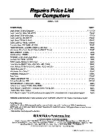
Page 4: ...b Section Computer Systems Division Limited Warranty 1 TS 806 Theory of Operation includes TS 806H TS 806 20 and TS 806H 20 2 TS 806C Theory of Operation 3 System Repair Price and Spare Parts Price Li...

Page 5: ...factured by TeleVideo only the warranty if any given by the manufacturer thereof applies EXCLUSIONS This limited warranty does not cover losses or damage which occurs in shipment to or from Buyer or C...

Page 6: ...n describes the hardware layout functions and operations Section 1 0 2 0 3 0 4 0 s o 6 0 7 0 8 0 TABLE OF CONTENTS Title Introduction General Description Function Circuit Description Connect r Configu...

Page 7: ...20 megabyte Winchester drive in the same style cabinet as the TS806 Both systems use the WD lOOO disk interface board The TS806 can be expanded with the TS 806H and the TS806 20 is expanded with the...

Page 8: ...e ZSOA DMA Direct memory access controller chip is used for direct transfer of data between memory and peripheral I O like floppy disk Winchester hard disk etc f Memory Main memory available to user i...

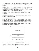
Page 9: ...power up or reset and are not acces sible by the users After the initial program in the ROM is run upon power up or reset the dynamic memory area address 00 16 K hex is switched on so that the whole 6...

Page 10: ...Hiud DiSk MiJl Floppy Disk Dl ives Winchester Htltd Disk COJltrolier Centronic type PriJl ter Interface DRAM 64kX8 l80A DMA l80A CPU O l AI RATE eTC 0 RS232C 1 RS232C I II l J 2 BAUD RATE t L J SwrT...

Page 11: ...0 0 X X X 40 WDC Reset Winchester Disk Soft Reset 0 1 0 1 0 X 0 0 50 510 0 ChA Data Reg 1 0 52 Com Stat Reg 0 1 51 Ch B Data Reg 1 1 53 Com Stat Reg 0 1 1 0 0 X X X 60 Baud Rate Load 0 1 1 1 0 X X X 7...

Page 12: ...ector Reg 1 1 B3 Data Reg 1 1 0 0 0 X 0 0 CO PIC Ch 0 CTC User Option 0 1 C1 Ch 1 1 0 C2 Ch 2 1 1 C3 Ch 3 1 1 0 1 0 X 0 0 DO PIO Ch A Data Reg 1 0 D2 Corn Stat Reg 0 1 D1 Ch B Data Reg 1 1 D3 Corn Sta...

Page 13: ...h POSe Baud Rate 4 3 2 1 19 2 KBaud 0 0 0 0 9 6 KBaud 0 0 0 1 4 8 KBaud 0 0 1 0 2 4 KBaud 0 0 1 1 1 2 KBaud 0 1 0 0 600 Baud 0 1 0 1 300 Baud 0 1 1 0 150 Baud 0 1 1 1 75 Baud 1 0 0 0 Table 2 Baud Rate...

Page 14: ...and data bus float and the control signal outputs are in active The CPU returns to normal operation after two internal T cycles Reset clears the PC register so the register now contain s a value of 0...

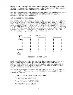
Page 15: ...e the ROM and SRAM When the ROM and SRAM are enabled CAS signal for dynamic RAM column address goes inactive disabling dynamic RAM OOH l6KH so only ROM and SRAM are active During read write operations...

Page 16: ...d previously when dynamic RAM is enabled it activiates CAS signal so that all DRAM locations can be accessed by the user During refresh only RAS signal is acti vated and one whole row is refreshed at...

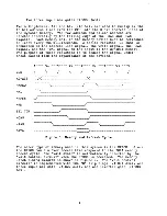
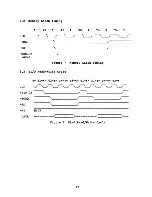
Page 17: ...READ Cyel I WRITE CYCL J I I Ao A 5 MREQ V v ROMCE Y GOns 7YI YI DATA 1 V ROM 9071S YVlo x WR IOOll 111 x r SRAH CS 1 I 23071S 1 l1 X DATA I 701lS n i71 WAIT V SRAM Figure 6 Read Write on ROM and SRA...

Page 18: ...S DATA ClK Ao I s ns m II It ISO 1 lS 7Yl X IOOl l m 00 1I57n X f I O llSm X I I 9 TlS l1lO X 11 70 l1s 7Il X 71 m x I 90113 me If J Figure 7 Instruction Fetch from DRAM MREQ 10 RD WR DATA Figure 8 Re...

Page 19: ...s soon as the current CPU machine cycle is terminated and then sends out BUSAK signal to indicate that DMA can control these signals Figure 9 illustrates the BUSREQ and BUSAK BAI timing The RDY line i...

Page 20: ...__ X ______ MREQ rv RD r v DATA rv Figure 10 RDY Line in Burst Mode Refer to I O Operation for precise timing RDY J V I 6USR N ___________ J r BAY _________ J r X Ao Als X _ c x r rv r v MREQ RI DATA...

Page 21: ...ficient time for an I O port to complete a read write operation One SIO A82 is for RS232 interfaces and its related chips are 75188 for output and 75189 for input The other 3 SIO s A61 A83 A84 are for...

Page 22: ...that the data register contains assembled data in the read oper ation or the data register is empty in the write operation This signal is reset when serviced by the system through reading or loading t...

Page 23: ...DMA read operation WD 1000 controller board is used for 5 Winchester disk interface As with the floppy disk controller WDe DRQ signal is used to control the RDY line of DMA by being NANDED with other...

Page 24: ...cs WPRQ WWE r 1 0 READ t MEM WRITf t J T T2 TW l T T I T I T I 200 l s11 l _ l S 7 S I 100 s YrI X Figure 15 woe To Memory Transfer OMA Read Operation I I 20011 S 1 IIAX f 100 1 1 1 I IOIx 25 1 s x Fi...

Page 25: ...nnector P1 P2 P3 p4 P5 P6 P7 P8 P9 P10 P11 Pl2 P13 Description Power RS232C Service Terminal Interface RS232C Serial Interface Centronics type Printer Interface Winchester Disk Controller Interface Re...

Page 26: ...2 RS232C Connector P2 3 25 Pin Pin No 1 2 3 4 5 7 8 20 Description DCE P3 Frame Ground Transmit Data Receive Data P3 Receive Data Transmit Data P3 Request to Send Clear to Send Signal Ground Data Carr...

Page 27: ...lect 0 Drive Select 1 Drive Select 2 Motor On Direction Select Toward Center Off Center Step Composite write Data write Enable Track 00 write Protected Composite Read Data Side 1 Select Ignored by one...

Page 28: ...2 7 WDAL 3 9 WDAL 4 11 WDAL 5 13 WDAL 6 15 WDAL 7 17 WA 0 19 WA 1 21 WA 2 23 wcs Winchester Chip Select 25 WWE Winchester Read Enable 27 WWAIT 29 WINTRQ Interrupt Request 35 WDRQ Data Request 37 WMR M...

Page 29: ...ey are connected together Refer to Figure 18 for comparison of two connector pin assignment between 40 pin connector on the board and 36 pin connector on the rear panel which will be hooked up to the...

Page 30: ...1 34 32 D iJ 7 W9 17 33 35 34 18 35 36 36 Second pin number indicates return ground Pin 37 38 39 and 40 are not connected Ground if no connection Tie high if no connection Description Data strobe Outp...

Page 31: ...P8 to P12 connectors are 16 pin header type but these are connected to the D type on the rear panel eventually The difference is only due to the different numbering order between those two types Refer...

Page 32: ...Manufacturer a Signal GND Table 9 D Type Configuration for RS422 b pa to P12 header type 16 pin Pin No Description Description D Board D Board Conn Conn 1 1 Shield 9 2 TXD 2 3 TXD 10 4 RXD 3 5 RXD 11...

Page 33: ...LED s are used for diagnostic purposes They are lit when the data line goes low The corresponding port address is 00 the data byte assigned to each LED is as follows LED No 1 2 3 4 Data Byte FO Fl F2...

Page 34: ...the printer interface does not need this signal Connect when the printer interface does not need this signal Connect when the printer interface does not need this signal Connect when the printer inte...

Page 35: ...All power for the board can be supplied from a single S volt power supply on a separate connector All host to disk data transfers are buffered by onboard RAM to achieve totally asynchronous transfers...

Page 36: ...nsure the data remains stable during the entire instruction This data selects a read strobe and write strobe through two 1 of 8 decoders U20 and 026 which are alternately enabled by the WC control str...

Page 37: ...h drives a Schmitt trigger U3l to provide a proper rise fall time on the RESET line of the 8X300 Alternate reset of the processor can be accomplished by dropping MR J5 pin 39 whenever the host wishes...

Page 38: ...512 bytes 8 2 6 2 Sector Buffering All data read from the disk or written to the disk is passed through the RAM to provide buffering required for asynchronous data transfer between the host and disk T...

Page 39: ...technique This technique requires clock bits to be recorded only when two successive data bits are missing in the serial data stream This reduces the total number of bits required to record a given am...

Page 40: ...erefore set to an open loop frequency of 2X RCLK Any variations in this rate due to variations in disk rotational speed must be compensated for by the VCO Instantaneous shifts in data due to the effec...

Page 41: ...0 to determine the condition of the MFM data stream The data and clocks are now connected to the first stage of the data separator The heart of the data separator is the VCO U2 and associated circuitr...

Page 42: ...The diode then receives and lower VCO The operating point of the tuning diode CRI is initially set for an open loop VCO frequency of two times RCLK by setting OSC ADJUST and monitoring the VCO output...

Page 43: ...dition When the circuit is balanced either both pumps are on or both pumps are off producing no net pump up or down 8 3 8 Window Extension Once the VCO has been locked onto the phase of the incoming d...

Page 44: ...d or data field Whenever SEARCH is dropped the VCO to RCLK divider is once again reset and no RCLKS are produced 8 4 Data Conversion and Checking MFM data which has been separated to form NRZ data and...

Page 45: ...rcuitry The AMOET signal remains true until the processor again de asserts the SEARCH control line 8 4 2 Serial to Parallel Conversion After an AM has been detected the Serial to Parallel converter U2...

Page 46: ...read on the disk The polynomial used is X16 X12 X5 1 commonly called the CRC CCITT polynomial During read operations the processor polls the condition of the DRUN circuitry When DRUN is true it begin...

Page 47: ...a convenient latching function for the CRCOK flag which mains true for at least 1 byte after the last CRC check byte gi ing the processor time to read the flag The data clock and BDONE are supplied t...

Page 48: ...used as the clock for the CRC device Whenever it is desired to write a repetitive string of identical data bytes the processor can simply ignore the BOONE flag and permit the device to reload the dat...

Page 49: ...device accepts NRZ data and a complimentary WCLK It also produces MFM data and clocks by sending the data through circuitry which decides when and where to write clocks on the data stream under the M...

Page 50: ...the present bits to be written and producing three signals depending on what these bits are The three signals are EARLY LATE and NOMINAL They are used in conjunction with a delay line to cause the le...

Page 51: ...ad or to store data on a write This time varies depending on the amount of processing the 8X300 must do to access the desired register After the data has been written or read the WDlOOO de asserts the...

Page 52: ...rations and Data ReQuests DRQ to signal data ready to DMA controllers INTRQ and DRQ originate on the MFM generator U30 as an auxilIary function of the chip The WDlOOO sets INTRQ using INTCLK and sets...

Page 53: ...fter the range has been verified adjust R22 to the final setting listed in the table Yl Frequency Identity Range Final Setting 20 000 MHz Ll 3 3 uh 9 0 11 0 MHz 10 0 MHz 1 KHz 17 360 MHz Ll 3 9 uh 7 5...

Page 54: ...ntil the most stable display reading is obtained This indicates that the VCO is being locked on every attempt to read data 3 Turn off power to the board 4 Disconnect all test equipment 8 7 4 DRUN Adju...

Page 55: ...4 Turn off power to the WDIOOO 5 Disconnect all test equipment 50...

Page 56: ......

Page 57: ...R and sets the interrupt status to Mode O During reset time the address and data bus go to a high impedance state and all control output signals go to the inactive state Note that RESET must be activ...

Page 58: ...IS 16 6 10 10 II 15 15 10 14 19 23 23 18 21 16 L h 00 BC 01 DE 10 HL II SP 00 BC 01 DE 10 HL II IJ Load lfL Imo 01 _ _ dacrwmM d tbiI brte _ 1lCl UBC 0 UBC 0 2 Exchange Block Transfer Block Search Gro...

Page 59: ...DE 10 IY II SP Rot Ie efIctrcu lor accumuililor Rotate left accumulotor Rototertqhtcireul4r occumulolor Rotateriqht ao umuililor RoI4leleilclfcul sr reql 001 C 010 D 011 I 100 H 101 L III A lnatrucllo...

Page 60: ...sse HL X X X X I X I X blllnCTemeni abat decrement 16 blladd RLA RLCA RRA RRCA RL m RLC m RR m X I X X P 16 b ladd wilhcarry I bllsublract wllhcarry RotateaCCllmuletor Rotate and shih locaiLonl RRC m...

Page 61: ...urn from interrupt instruction RET ED 4D sent by the CPU During two byte instruction fetches III is active as each opcode byte is fetched An jnterrupt ack nowledge is indicated when both III and ORO a...

Page 62: ...Strobe Pulse From Peripheral Device input active Low The meaning 01 this signal dependo on the 01 operation selected lor Port A as lollows Oulpu Modo The iUve edge 01 this strobe _ by the per1pherol...

Page 63: ...EO o I MOD I 1 0 O I 1 I MODE3 FIll B Mode CoD 1 W ffiDOJ o J D LID VECTOR VECTOR FIll 7 IDIettupt V W T J ID c 0 lETS liT TO OUTPUT 1 lETS liT TO INPUT Fill 8 YO lIogIotor Co IroI W fO Jii EF Jil E C...

Page 64: ...ued the trigger mode for timer operation When OJ is reset to 0 the timer is triggered automatic ally The time constant word is programmed during an I O write operation which takes one machine cycle At...

Page 65: ...either data or control Information as speCified by cm If 10RO and MI are active simultane oiisly the CPU is acknowledging an interrupt and the 510 automatically places itl Interrupt vector on the CPU...

Page 66: ...hree bits Do D that point 10 the selected regiSter the second byte Is the actual control word that Is written Into the register to cor figure the SIO WRO is a special case in that all of the basic com...

Page 67: ...ON SECTION TITLE 1 0 INTRODUCTION 2 0 TS 806C TAPE CONTROLLER BOARD DESCRIPTION 3 0 FUNCTION OF THE SYSTEM 4 0 OPERATION OF THE SYSTEM 5 0 INPUT OUTPUT PORT ASSIGNMENT AND TIMING 6 0 CONNECTOR DESCRIP...

Page 68: ......

Page 69: ...ation The TS 806e receives commands from the TS 806 to perform tape read write or erase functions all other data is passed through to the work station The system block diagram is shown in Figure 1 1 1...

Page 70: ...en by a 4 MHz system or tape clock This clock is also used to generate the necessary timing for the memory control logic The Z80A CPU has a 16 bit address bus which can address up to 64 Kbytes for mem...

Page 71: ...ins eight 64K x I jynamic memory devices only 60 Kbytes are accessible There are four kilobytes of EPROM 3 0 FUNCTION OF THE SYSTEM rhe TS 806C generates an 8 MHz clock and a 4 MHz clock These are sup...

Page 72: ...the Z80A devices The high level of the clock must be between 4 4 V and 5 3 V and the low level must be between 0 3 V and 0 45 V see Figure 4 A transistor 2N2907 is used to pull the clock s output high...

Page 73: ...memory The purpose of these resistors is to reduce the signal under shoot caused from the capacitance of the devices Tl T2 T3 T4 CLK 1 _ _ J 1 1 11 ___1 AO A15 _______x_________ MREQ __ __ 11 ________...

Page 74: ...rols the tape drive operation 4 1 1 Output Latches from the computer The control signals to the tape drive are programmed by two data latches These latches are write only ports 4 1 1 1 Tape Output Lat...

Page 75: ...X 1 RWD I FB 1 WEN 11 HSP 1 FWD REV 07 06 05 04 03 02 01 00 Reverse direction REV is 000 Active low causes the tape move in the reverse direction Forward direction FWD is 001 Active low causes the tap...

Page 76: ...1 2 Input Latches to the controller The status of the tape controller is read through two input ports These ports are read only status line which are latched by the tape drive 4 1 2 1 Tape Status Inp...

Page 77: ...ard or reverse command This signal goes true when the command is received and remain true until tape motion has stopped The time for slow speed commands is 30 milliseconds and for high speed commands...

Page 78: ...e low on the SIO for the equivalent of a five byte transmission time before and after the data is transmitted During data transfer DTR is at a high level 5 0 Input Output Port Assignments and Timing 5...

Page 79: ...LK J I 1 1 I IORQ WR MEMORY LATCH I I _ _ _ _ I Figure 7 Memory Latch Timing 5 3 SIlO Read Write Cycle Tl T2 TW T3 Tl T2 TW T3 CLK J J I I I I J I SID CS IORQ ____ I RD Ml HIGH DATA ________ _________...

Page 80: ..._P2_ 5_ PI P4 __ _P3_ __________ Figure 9 Connector Positions Connector No PI P2 P5 P3 P4 Legend 13 Description POWER CONNECTOR RS422 CONNECTOR TS806 RS422 CONNECTOR TS800 TAPE INTERFACE CONNECTOR RES...

Page 81: ...16 pin header on the PCB Rear panel 15 pin D type conn D conn Header Description 1 1 GND 9 2 TxD 2 3 TxD 10 4 RxD 3 5 RxD 11 6 RTS 4 7 RTS 12 8 CTS 5 9 CTS 13 10 TxC 6 11 TxC 14 12 RxC 7 13 RxC 15 14...

Page 82: ...nnector 5 Pin Wafer Option PIN 1 2 3 4 5 7 0 SPECIFICATIONS Power Requirement Power Consumption DESCRIPTION C Opt n for lighted switch Void No pin Reset Signal Ground NC Not used 1 08 Amp 5 V TYPICAL...

Page 83: ...Interrupt Priority 1st Priority SIO 2nd priority CTC 16...

Page 84: ......

Page 85: ...E LISTS This section contains the Repair Price List for Computers and the Systems Spare Parts Price List in effect at the printing date of this manual Use these lists for estimating repairs prices are...

Page 86: ......

Page 87: ...c Repair charge This additionalamount charged when an entire system is returned for repair Te eVideo will bill perabove price schedule when no trouble is found in the module returned for repair Outof...

Page 88: ......

Page 89: ...Systems Spare Parts Price List o TeleVideo Systems Inc...

Page 90: ......

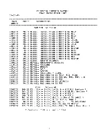
Page 91: ...r s TS 802H Installation User s TS 803 Installation User s TS l602G Installation User s TS l602GH Installation User s TS 1603 Installation User s TS 806 Installation User s TS 806 20 Installation User...

Page 92: ...e TS 803 1603 866 19 PCB Asy 5 n Winchester Disk Controller 806 806 20 866 19 PCB Asy 8 n Winchester Disk Controller 816 40 210 75 PCB Asy Floppy Disk Cont TS 802 Daughter Bd 656 87 PCB Asy Graphics T...

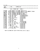
Page 93: ...2100600 110 00 Case Top TS 802 1602G 2100700 85 00 Case Bottom TS 802 1602G 2100800 40 00 Bezel TS 802 1602G 2141700 70 20 Case Bottom TS 800A 2141800 97 80 Case Top TS 800A 2141900 20 00 Bezel TS 800...

Page 94: ...40 IC I O Decode TS 1602G 55 80 IC Diagnostic EPROM TS a06 55 aO IC Diagnostic EPROM TS a06C 55 80 IC Diagnostic EPROM TS a16 55 80 IC Diagnostic EPROM TS 816 40 23 70 IC L2 7 System Program ROM WDC...

Page 95: ...50 57 Pin TS 816 40H Internal for Winchester 2235600 42 36 Cbl Asy 25 20 Pin TS 816 40H Internal for Winchester 2008600 28 00 Harness Asy Power TS 802H 2007900 28 00 Harness Asy Power Cable 16 ft TS...

Page 96: ...Crystal 15 MHz 2042800 27 00 Crystal 16 MHz MOT CTS HYT 2098604 4 50 Crystal 20 000 MHz 2035200 37 08 Crystal 23 814 MHz Kll14A MOT CTS 2099700 1 02 Insulator Mounting Pad For Crystal FANS 2099000 35...

Page 97: ...S 1 50 Label Logo Plastic TeleVideo Systems 2 40 Label Logo Plastic TeleVideo Printer 72 Label Keyboard TS 800A 72 Label Keyboard TS 802 72 Label Keyboard TS 802H 72 Label Keyboard TS l602G 72 Label...

Page 98: ...oltage Inductor 27uh Voltage Regulator LAS 16CB 2A 13 8Volts Resistor CF 390 Ohms 1 2Watt 5 IN759A Zener Diode Capacitor 220uf 16Volt Electrolytic Capacitor luf 600Volt Mylar 2SC2233 MJE13006 Diode 30...

Page 99: ...806 Logic To Floppy WDC To Winchester 806 Logic To WOC 806 WOC To Winchester 806 Parallel Printer Spare Parts Mechanical TS802 800A cord for keyboard 3 amp 125V fuse 25 each keyswitch 10 position side...

Page 100: ......

Page 101: ...latest board assembly drawings and logic diagrams When ordering parts use the component type or value shown in the diagrams to refer to the TeleVideo part number listed in the Spare Parts Price List T...

Page 102: ......

Page 103: ...r _y p o i f _ Gf i r M r c t C3S CD CD c 0 c iWI l t J i t r a rr 6 i h ot 0 J I r L ii LJ n a j CL_ C3 c I C S c JI c c I 5 IJi8 I c J r 1 l j 1 r 1 1 1r 1Tn1 T I I SCI c x c a5 d d C3 i ia i I w r...

Page 104: ......

Page 105: ...Z r D4 m U mET gz I p JSQ Ar 1t IAt I JL r I rw n 10 A 7 8 9 C M Z 7 6 1 1l a Ir ISIS J I AITFRIlM MlC Z A45 J itt IR I T 0 11 1 1 74LS3Z 0011 I IJ r ___ 4 d Z 1154 IV 51110 MI e 1t tHz S e n SN 3 __1...

Page 106: ......

Page 107: ...O Dl DI LI It C I PCl ORIT I PC 02 Iii QI t R 1 52a D o H e t _t j A V EO H _ e t 1 1 11 Rm 04 I P4 iBf 14 I U 6 40 DIj I D il m p L I 4 Jllii m OT sv o i 1 C1 C 1i a vc c I A zeDA crc Rt IK OW I ql e...

Page 108: ......

Page 109: ...A r 1 0 u S3Z It l IL108 11 M I 14L 08 1 A A 4LSOS V1l c Ui 8F I M M 1 wJ IT FROM woc A 811 AalS 814 5 iiIl Z H 8 7 6 5 4 3 51411 _ l V fl IK F 1 Ia I I In I I4Sl 500 _ Aoe I MIOO Y I n AU n I 11 I4S...

Page 110: ......

Page 111: ...r i ID Ut Col 0 0 0 iii Ii I 1 R ql i 8 15 _ I ID lE Hi i Ii i I t s g f s I s 1 E l I s E t I OOlZloZ I I ID l n I 0 I t I Ut 1 tnolD N I i Bil H 4 il l S l l t N Il 2 g Col t I N I T n I...

Page 112: ......

Page 113: ...Z STiP ZJ III l WI ii I Iso VICi fL A uc WF r J I CUC WJIlfT LAT ri 1 M rJI TGo4 1 c 54 R6 MLO ln IW T 1 iGI 5 4 3 J 0 IV J _0 o _ J J l C _0 f P 7 A OIC A IOIC A 14Lt04 A64 II 41 e 14Il00 DKJ ll I J...

Page 114: ......

Page 115: ...o til cONPOsnE WAITE OATA 3 12 04 L Pll 21 c s 0 10_ tL Z H SH5 HZ 50 Cl _ SF AS7 s 4U74 a 03 R 33 mm 0 SH5 a i S b l 7 1 I _ A A __ __ _ l8IeYtcIeo lnc I 1 1 PcB SCHEMATIC ___ FI I TS B06 CMP BD DI J...

Page 116: ......

Page 117: ...to I 1 0 J M IQO t I 0 Pet I Pq j Pq P 4 p PldI PI J Ple I PIO 4t Pt l Pte C C IU t 1 II I A _I T O hOA TwO A X f i t 4 A T OU t IS I iZl rmn 11 A l COlI r J I tIl I P 11 f IOO p Zt L S II IA au 84 r...

Page 118: ......

Page 119: ...J Tz SY II IA NOTE ON JUMPE I I W I CON T II TO C IF Rl ICe CDN IS QI E O UP T RU P Z t CDNNILC II IF ND SE II CE CXlN DUT l IDE PZ 14 f A tml aT fiiC8 ifoiZ7 6ND 4 ilJT Illm IIIl lEO 7 zv I TlrOIl U...

Page 120: ......

Page 121: ...I I II I I I I 1 co I 5 1 L __ ell _ E ti f t L 1 i C C t _ w w 0 I It I J E I N II II II u i 1Il I 0 0 1 1 r t C 0 III n S i i r 6 i 1 It N t 3s a Ci 1l 0 c 2 1Z II I I I I r E E J i I oJII 8 n f t...

Page 122: ......

Page 123: ...Z Zl fi5iRI 5 4 DIP t o t PTOIt 2 PW DW I It su I 11 I t s G DlI tr 1 I SIlO 1110 f 6 1S f M o p 1 1 I S I D D e I iil5tWl l 9 MLU WWZ1Ii AU p J 1 WWIJf cfill bJ lcJ Tt P iiII lWlit II Nbc Zt toR _Ij...

Page 124: ......

Page 125: ...gJ 100_ J I Ot zw S3 Z lft1 Ptl I Pta I 1i r tk OS IIlIII A I PII Pit 1 oU fin In I 110 fii t 100 T I I O IID 100 za R a TOn Til j z L lllffilba DY i9ID p L mfJT1I6Y pia PIC 8 t lI 2 2 111lj 1m y l D...

Page 126: ......

Page 127: ...m rr _ mt B rnt 0 I I rn n d IO 7 e 0 iiiji om mt J tt i iiiAU U I O e I 0 oij1 if ii mJe U rJ rE o i i 8 m I V N o ru iO II m PsI r1 I l W 1 1 m eD51 I f enl 11 C 1 Q Ss I ilia I I 1 n GO CI I w I d...

Page 128: ......

Page 129: ...1 A31 116 IN914 RI2 n 6 I lU SI38 1 Z I A33 74L527 R VISIONS 5HZ 5 13 5V l lllESS OTiERilISE SPECIfiED Ql e I PI SIP R ISTOR 220 330 IM I V MREQ I A vee y IS 1 31 6 SIlZ f SZ41 stl B A26 1 1 14 P i 3...

Page 130: ......

Page 131: ...1 II Z 4 4 Z 3 12 A3 12 A 12 A 10 I A Z I 3A All3 0 6 A1 A2 AZ b A2 9 6 ZB74S1S7 7 1 1 7 A AI 7 AI 2A zt I AI 3 S AlP S 119 S 1 1 Ro 3 w 3W 3 W 3 W AD RI1 I RAS NiO i C 5 CA 5 GIlt I I EPRDM EN 3311 B...

Page 132: ......

Page 133: ...CTC Mi 0 liD __ I C CI jffi NT lllC fq _RN l P3 36 t 1 f no i i 4 l 4 J S P 4Z e IA 16 1 17 74 16 p741S ll tJ lEI IS li RTS I 9 S 74L S04 I i3 T P3 44 H r l y I U _ _ _ _ 1 P F w I 74L S041 15 10 I U...

Page 134: ......

Page 135: ...S II ell m 1 5 10 Til 7 _c 1 PS 3 26LS lZ I O P i z HO 0 IS R S P5 1 _ RTS P5 7 RTS J A ourM I L _ _I 1Lf RiC SIc OUTPuT A4z ZloLS lZ RiO 13IS OUTPUT P5 13 RXC pZ 7 t RlD PZ 14 l i r n m IA OUTPuT TXD...

Page 136: ......

Page 137: ...3 7 J II PI 8 U r 7D nDEEJ I Q O e I I i J I L d CED 6C I l I Oli k i iy ltem Inc UOM 5 WDC 11 11 11 III 11111 It v I Ui il o B TOP Vltw SIDE VIEW NOTE UNLESS OTHERWISE SPECFlED 1 COMPLETE HEIGHT NOT...

Page 138: ......

Page 139: ...SELEcT BITS 4 1 DRUN D T RUN HFRQ HIGH I R1ii QUENCY r _ _ 1IOlU _ _ HO T SELECT NXlSS CONTROL J HSZ HS HUID SELECT BIT 2 tf I RESISTOR VALUES ARti IN OHMS lSI V4 w ri v IAt INSTRUCTION ODRESS UNES B...

Page 140: ......

Page 141: ...UI SH3 5 8 R_E_S_EI ___ SH3 MelKI 1 rO 106 o 1 0 SH14 S B rO 3 1 0Z ol ro 1 III r M UI n o...

Page 142: ......

Page 143: ...c S Q II e Z 3 I I 1 I ZQ G rt 5 fIfI s II A I 1 1 1 6 I A5 Z 1 4 IO IOZ At rt I 101 11 f ro Po r c A I 1 C A I AS 2 MI3 II IO r _ IOZ liZ 7 Tll P lID I I n I I t I Q N CO 1119 I CJ 1 91 I IiIB I 01 G...

Page 144: ......

Page 145: ...J1 ZZ SIll SH7 Slil 5H cs RE ii R6 RDb NoEll T V CI 00 SE EK COMPLETE LT J l tRSEL JZ J3 1 l J4 1 i 7 SitS 6 5 4 3 J5 Z J5 4 J5 6 15 8 JS IO JS IZ JS 14 JS 16 JS 18 JS ZO l I J5 2 j 211 J5 32 JS 34 5...

Page 146: ......

Page 147: ...lusS OIRECTION IN WR 7 1uz0 q L 7438 r________________ CS A C WilEN r fLS08 I lJa U ll z rsv rl DRq cs _ V o fq 6 74S r4p Pf44 rls SI4r L4 _ IQ R41 U 1 T 74504 l INTRQ t J I U54 lJ44 _6 14lS14 W IIT A...

Page 148: ......

Page 149: ...RCLK SH8 lli L SH8 TPII RID I __ B 1 li 8 V z s T eLKS SH 8 SHl i 5V 1 1 h J6 4 t lMi L iY m I _ le16 1 f2 fi I 5 TP8 3 30 H Clc I J lfi i sv I v _ G 0 J 3 I W ll__ _ t t ___ SId y I J I I Z I N I L 0...

Page 150: ......

Page 151: ...UPI 5 t5 1 f PUPI 4 9 U18 TP3 1 1 UIS 3 2 PHASE DETECTOR G I SEE 5 E E T I y 6 PUPI TPI8 4 ilQ U18 o p1 5Sb 74551 TP4 PUPI A74 4 I GND 17 us r74s r 13 RUN SH 8 lEL oH 5 5HOT 5HB 10 9 8 1 H6 c sS6 DRUN...

Page 152: ......

Page 153: ...05 _ lOb U30 001 13 r9 8 01 CRce_l_ 14 WOllOO 2 U29 DCLI WCC R wDIiOO OOI ICLI fiDl EN I 3 WCll 15 BDoN 16 Id NTCLI 5I f cs EN A j wRnE L 9 I SH3 AI I I INTRQ SHS 1 DW Cft U1 DI Q SHS All DETECT MR 11...

Page 154: ......

Page 155: ...TIM eLI 374L5S4 IWB J 1 9 OUT IW J uu lJfB 5 TI I eLi J 1 10 R3 240 6ND GNC 4LSS4 10 0 WRITE DATA j _ 1 1 4 OUTet II NI lTE DATA j I i J OUTC EN J3 14 H8 EARL NoM EN LATE J 1 2 J3 Z Jh1 J3 4 JI 6 J3...

Page 156: ......

Page 157: ...5 4 TID 3 2 OB 001 vcc vee RETURN ve vcc 334 24 204 3 N f_o T n i LI 12V V 1 1 SV _ II I W I I I m J I C41 l 1 12V 4A MAX 7 Li I l h IRfT 1 I Y I 1 I IlV II till J A 6 3A MAX o I I I t _ _J 1 1 11 11...

Page 158: ......

Reviews: