2
WARNING: NEVER image the sun or point the telescope toward or near the sun without pro-
fessional solar equipment rigidly secured in front of the objective lens. Remove any sighting
devices such as Starbeam from the telescope. Use only the Tele Vue Sol Searcher to find the
sun. Instant and permanent eye damage may result from viewing the sun directly, even during
a solar eclipse, or when viewing through thin clouds, or when the sun is near the horizon.
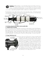
Standard Features - Optical tube assembly includes: captive sliding dew shield, , tilt adjustment end plate
with integrated Zero Tilt Adapter, front and rear screw-on metal lens cover (not shown), universal tube rings,
custom hard-shell case, Allen Keys for end plate tilt adjustment.
1.0 Getting Acquainted with the Tele Vue-NP127fli
1.1 Optical tube assembly
The NP optical design contains four elements consisting of two widely spaced, air-spaced doublet groups.
The forward group of lenses are contained in a stainless steel lens cell. The cell attaches to the main tube via
three alignment screws. The front cell is encased within the sliding dew shield. The rear doublet, making up
the rest of the objective, is larger in diameter than the previous NP127 and provides additional illumination
at the edge of the field. This benefit is especially useful for large format CCD chips which are extremely
sensitive to light fall-off. The rear lens group is housed in the cell that threads on to the back of the tube.
1.2 Large Field Corrector
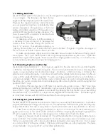
The placement of the large field corrector lens at the very end of the OTA is critical to the edge of field
performance and is dependant on the camera used. The lens
assembly has been factory set and locked to be properly spaced
for the back focus of the combination of Atlas focuser, CenterLine
filter wheel, and ProLine series cameras. These products have been
tested and proven together as a system with NP127fli. Should
you choose to adapt any other camera to this system or use any
other products, you may need to adjust the lens position. You may
do so by first loosening the set screw located in the knurled ring.
While holding the Large Field Corrector lens assembly, loosen the
knurled ring. You are now free to thread the Large Field Corrector
lens assembly in or out as necessary. To tighten the assembly,
hold the Large Field Corrector assembly in place and fully tighten
the knurled ring. Finish by tightening the set screw.
127mm Front
Lenses and Cell
Dew Shield in
retracted position
Main Tube
Rear Lens Cell
Supplemental Tube Ring
Large Field
Corrector
Adapter Tube
FLI Zero Tilt Adapter
Connection
Tilting End
Plate
Spacer Block
Adjustable Top Bar
Accessory
Channel
Main Tube Rings
Removeable
Mounting
Hardware
Locking Bat
Handle
Knurled Ring
Large Field Corrector
Lens Assembly
Tilting End Plate
with ZTA Adapter


