background image


15

Chapter 4: Configuring the Wireless CPE 


Overview 

 
The Telex wireless CPE is shipped with default (factory-set) values for certain network settings.  
You will need to change these settings at the client location to match those provided by your ISP 
or IS Department. 
 
To do this requires 3 main steps: 
 
1.  Change your computer network settings to match the default network settings in the CPE so 

your computer can communicate with the CPE. 

 
2.  Using a standard web browser (Internet Explorer 5.5 or later, Netscape 7.0 or la ter), change 

the CPE wireless network settings from the default values to the values provided by your ISP 
or IS Dept. so that your CPE can communicate with the Access Point or another CPE. 

 
3.  If necessary, change the network settings on the CPE and computer to match other devices on 

a wired network connected to the computer. 


If you do not know how to enable and change network setting on your PC, contact your 
network service provider (ISP or IS Dept.) support desk or a qualified PC technician for 
assistance. 
 

If your network service provider has not already provided you with specific network settings to 
use, contact them now and ask for the following: 
 
1.  The IP Address assigned to your CPE: 
2.  The corresponding Subnet Mask: 
3.  The corresponding Default Gateway: 
4.  The corresponding SSID and radio channel: 
 
If your network uses DHCP to assign IP addresses automatically, you may not need the IP 
address, Subnet Mask or Default Gateway. 


Summary of Contents for 2472AA

Page 1: ...Model 2472AA Long Range Moderate Power Wireless CPE Outdoor Bridge Instruction Manual Telex Communications Inc 8601 East Cornhusker Hwy Lincoln NE 68505 Rev A April 2004...

Page 2: ...ERSON AND SHALL C ONSTITUTE FULL SATISFACTION OF ALL CLAIMS WHETHER BASED ON CONTRACT NEGLIGENCE STRICT LIABILITY OR OTHERWISE TELEX s MAXIMUM LIABILITY SHALL NOT EXCEED THE ACTUAL PURCHASE PRICE PAID...

Page 3: ...g measures Reorient or relocate the receiving antenna Increase the separation between the equipment or devices Connect the equipment to an outlet other than the receiver s Consult a dealer or an exper...

Page 4: ...the Wireless CPE 12 Selecting a Mounting Location 12 Attaching the Mounting Bracket and Aiming 13 Routing the CAT5 cable 14 Connecting the Wireless CPE 14 Chapter 4 Configuring the Wireless CPE 16 Ch...

Page 5: ...gives you the freedom to place any standard networked computer anywhere within range of an access point A built in 18 dBi antenna and 50 mW radio means that you can easily cover distances of up to 8...

Page 6: ...mode Selectable MAC address cloning Selectable inbound and outbound bandwidth limiting from 64 Kbps to 1500 Kbps Signal and noise displayed in dBm quality displayed in Tx Rate Link quality signal str...

Page 7: ...llowing tools will be needed to assemble and mount your wireless CPE 7 16 nut driver or wrench 5 16 nut driver or wrench 3 4 wrench or adjustable wrench for grommet nut UV stable plastic cable ties or...

Page 8: ...f a length of exterior CAT 5 8 conductor Ethernet cable through this grommet Attach a standard RJ45 connector to the end of this cable using standard wiring for a straight non crossover connection Plu...

Page 9: ...e CAT 5 cable are secure then re attach the access panel to the CPE rear panel before proceeding The Power over Ethernet PoE injector The Telex Wireless CPE uses a PoE injector to supply DC power to t...

Page 10: ...hub switch or router is turned on This green LED will fast blink when passing Ethernet traffic The second green LED will light when a connection or association has been established to a wireless acce...

Page 11: ...AP The closest AP may not necessarily have the best path if it is blocked by hills buildings or trees Ensure that the chosen signal path has sufficient Fresnel zone clearance with respect to the grou...

Page 12: ...acket to obtain a 10 degree tilt either up or down If you require more than 10 degrees then use a standard DSS dish mount instead After aiming the bracket attach the CPE unit to the angle bracket usin...

Page 13: ...lowing the cable into the building Pull any excess cable into the building then weather seal the hole around the CAT 5 cable with quality exterior grade sealant Route the cable to the PoE location ins...

Page 14: ...witch or router and the first green LED is not lit then move the switch on the PCB inside the CPE to the other position If this LED is still not lit then check the wiring of the RJ45 plugs on the exte...

Page 15: ...r IS Dept so that your CPE can communicate with the Access Point or another CPE 3 If necessary change the network settings on the CPE and computer to match other devices on a wired network connected t...

Page 16: ...Address 192 168 1 100 Subnet Mask 255 255 255 0 Default Gateway 192 168 1 1 e Click OK to accept the settings f The NIC must be set to 10 Mbps and Proxy Server must be unchecked under LAN settings Re...

Page 17: ...onally to check for updates Select the Wireless Scan page to show available access points and their channel signal level and BSS Mode including WEP Press the Refresh button to update If your network S...

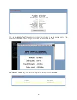
Page 18: ...n New Window to open a large font window for use in antenna aiming This window automatically updates every few seconds It should look like this The Ethernet Clients page will show all computers curren...

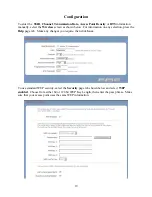
Page 19: ...own below For information on any selection press the Help page tab Make any changes you require then click Save To use standard WEP security select the Security page tab shown below and select WEP ena...

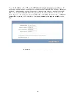
Page 20: ...s IP address after exiting the browser Otherwise the computer and CPE will not be able to communicate with each other They must be on the same subnet in order to see each other If you plan on having...

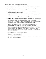
Page 21: ...rite down this information and store in a safe place so that it is not forgotten or stolen Any time that you wish to reset the CPE to factory defaults click on the Reset Configurationbutton on the Reb...

Page 22: ...gure a Syslog client which can send events and information messages to a Syslog server In the Reboot Reset page shown below you may use the Reboot button to immediately reboot the CPE The Reset Config...

Page 23: ...have been made and saved at the client CPE location close the browser Subsequent changes may now be made from either the client location or anywhere on the network as long as you are in the same subne...

Page 24: ...r that is one higher than the CPE IP address For example if the CPE s IP address is 192 168 1 99 then assign 192 168 1 100 to the computer If you have many computers and CPE s in your network then mak...

Page 25: ...items that affect the association of the CPE with the rest of the network If the association is lost then you may only communicate with the CPE from the local client computer These items may be easil...

Page 26: ...ck wiring Defective PCB in CPE Replace CPE unit Problem First Green light is on and system tray shows connection to the NIC but cannot load CPE log in page Possible Causes Solutions Proxy Server box c...

Page 27: ...ed requests Added BSSID and RSSI to syslog mark messages Improved RSSI and noise level dBm readings Fixed wrong MAC address displayed by Locator Now show the device the bridge is associated with on th...

Page 28: ...s 13 km at 20 dB SOM 1 Mbps Typical LOS Range approx 3 miles 5 km at 20 dB SOM 11 Mbps Security 64 128 bit WEP Electrical Specifications Operating Voltage from 9 to 24 VDC 12VDC supplied Operating Cur...

Reviews: