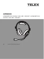
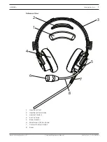
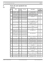
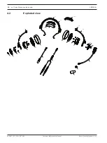
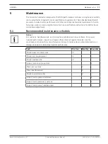
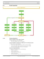
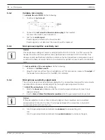
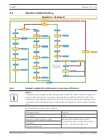
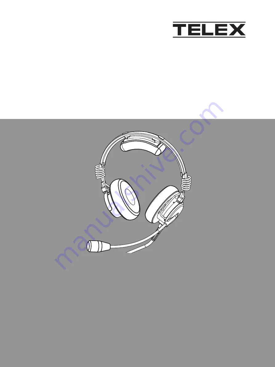
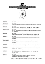
Telex AIRMAN8+ Series, Customer Maintenance Manual
The Telex AIRMAN8+ Series Customer Maintenance Manual provides essential instructions for the proper care and maintenance of your aviation headset. Download this detailed manual for free from our website, ensuring you have the necessary information to keep your headset in optimum condition for optimal performance.
Share
Download


Reviews:
No comments
Related manuals for AIRMAN8+ Series
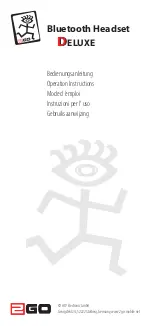
DELUXE
Brand: 2GO Pages: 20
B901
Brand: N-Com Pages: 33
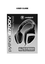
6700V
Brand: Python Pages: 8
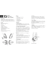
BH100
Brand: Xqisit Pages: 16
BT400
Brand: Able Planet Pages: 2
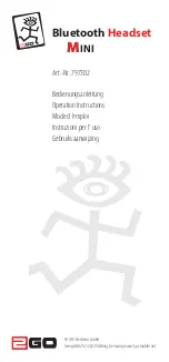
Mini
Brand: 2GO Pages: 12
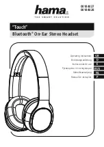
Touch
Brand: Hama Pages: 27
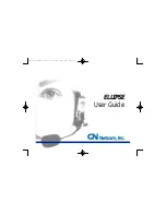
Ellipse
Brand: Jabra Pages: 12
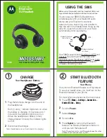
S805 - -QSG-EMEA
Brand: Motorola Pages: 6
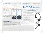
HC100
Brand: Sangoma Pages: 2
ONE
Brand: XBOX Pages: 13
H9
Brand: Ibml Pages: 2
Steel
Brand: Jabra Pages: 20
KX-TGA106M - Cordless Extension Handset
Brand: Panasonic Pages: 6
RP-HTX80B
Brand: Panasonic Pages: 2
WXCH2050 - WIRELESS ORDER TAKER
Brand: Panasonic Pages: 12

BT160
Brand: Jabra Pages: 2
BT160
Brand: Jabra Pages: 2


