6
Installation
Unpacking
The package contains the following items. Contact the shipper or your Audiocom® dealer immediately if anything is
damaged or missing. Detach and fill out the registration card and return it to Telex to properly register the product.
PS-2001L
Qty
Description
1
PS-2001L Power Supply
1
Warranty and registration card
1
User Manual
4
Rubber Feet (install for desktop use of the PS-2001L)
1
Power Cord
SPS-2001
Qty
Description
1
PS-2001L Power Supply
1
Warranty and registration card
1
User Manual
4
Rubber Feet (install for desktop use of the PS-2001L)
1
Power Cord
1
RCA to RCA Patch Cord
Configuration Switches
The
BAL / UNBAL
switch (located on the rear of the unit) is set to the Balanced (Audiocom) position when the unit
is shipped from the factory. To set the switch to the Unbalanced (Clear-Com) mode, use a pointed object such as a
pen to push in the switch.
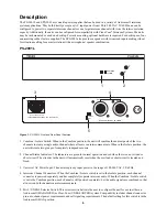
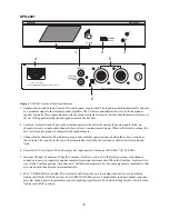
The
Combine / Isolate
switch (located on the front of the unit) can be changed at any time by using a pointed object
such as a pen to push in the switch. When the switch is in the Combine position, all users on both channels may
intercommunicate. When the switch is set to the Isolate position, channels 1 and 2 cannot intercommunicate.
Intercom Channel and Program Connections
Channel Capacity:
When connecting intercom stations to the PS-2001L or SPS-2001, determine the total current
for all stations on each channel. The total per channel should not exceed 2A. If you exceed this limit, an overload
indication will be provided and the output of the power supply will be turned off. Once the overload is corrected, the
overload indication will disappear and the power supply output will be turned on. Note that if you are using DC
wallpacks with some intercom stations, you do not need to add the current consumption of those stations to the total
current.
Audiocom Connections:
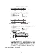
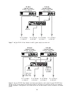
Intercom Cable wiring details are shown in Figure 3. Speaker interconnection cables
(SPS-2001 only) are standard RCA phono types. For program input cable wiring, refer to your master intercom
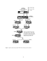
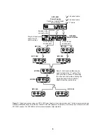
station user manual. Some typical intercom applications are shown in Figures 4 through 8.
Clear-Com Applications:
Refer to your Clear-Com system documentation for intercom cable wiring and connection
details.
Desktop or Rackmount Installation
For desktop use, install the four supplied rubber feet to the bottom of the unit. Do not obstruct the cooling vents
when using the unit on a desktop.
For rackmounting, use an optional Audiocom Rackmount Kit. Several kits are available to meet the requirements of
your particular system. Follow the assembly instructions supplied with the rackmount kit.


