background image


xE922-3GR 

Hardware User Guide  

1VV0301272

   Rev.0.8 - 2017-01-05 

Summary of Contents for E922-3GR Series

Page 1: ...xE922 3GR Hardware User Guide 1VV0301272 Rev 0 8 2017 01 05...

Page 2: ...Guide 1VV0301272 Rev 0 8 2017 01 05 Reproduction forbidden without written authorization from Telit Communications S p A All Rights Reserved Page 2 of 112 APPLICABILITY TABLE APPLICABILITY TABLE 1 PRO...

Page 3: ...erve for Telit and its licensors certain exclusive rights for copyrighted material including the exclusive right to copy reproduce in any form distribute and make derivative works of the copyrighted m...

Page 4: ...translated into any language or computer language in any form or by any means without prior written permission of Telit High Risk Materials Components units or third party products used in the product...

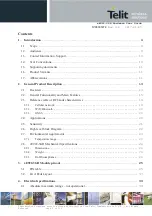
Page 5: ...t Description 13 2 1 Overview 13 2 2 General Functionality and Main Features 15 2 3 Reference table of RF bands characteristics 19 2 3 1 Cellular network 19 2 3 2 WiFi Bluetooth 20 2 3 3 GNSS 20 2 4 A...

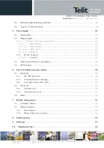
Page 6: ...5 2 1 3 VAUX_3P0V 43 5 2 1 4 VSIM1 2 44 5 2 2 DC DC stepdown 44 5 2 2 1 1V8_OUT 44 5 3 Typical system power consumption 45 5 4 RTC backup 47 6 Power ON OFF and reset control 49 6 1 Power On 49 6 1 1...

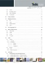
Page 7: ...2C 71 12 2 USIF 72 12 3 SDMMC SDIO 74 12 4 ADC 77 13 General purpose I O 78 14 Debug flash interfaces 81 14 1 USB2 0 HS 81 14 2 USIF2 81 14 3 JTAG 81 14 4 Test pads 81 15 Audio 82 15 1 Analog 82 15 1...

Page 8: ...on your board 96 17 1 General 96 17 2 Finishing Dimensions 96 17 3 Recommended foot print for the application main board 97 17 4 Stencil 98 17 5 PCB Pad Design 98 17 6 Recommendations for PCB Pad Dime...

Page 9: ...ument cannot embrace every hardware solution or every product that may be designed Obviously avoiding invalid solutions must be considered as mandatory Whereas the suggested hardware configurations ne...

Page 10: ...e you can buy the Telit modules or for recommendations on accessories and components visit http www telit com To register for product news and announcements or for product questions contact Telit s Te...

Page 11: ...l intel com 1 6 Product Variants xE922 3GR is available in the following hardware variants Type Number Description HE922 3GR GSM GPRS EGPRS WCDMA HSPA WiFi BT GNSS WE922 3GR WiFi BT GNSS 1 7 Abbreviat...

Page 12: ...SP Image Signal Processor IDI Inter die interface LE Low Energy LVDS Low Voltage Differential Signaling MIPI Mobile Industry Processor Interface MS Microstrip line PMU Power management unit SD Secure...

Page 13: ...GFX core modified Mali 450 MP4 600 MHz 128KB DSP 2x TeakLite 277MHz Media Encode Decode Engine modified VeriSilicon Media Engine dec G1 enc H1 Video encoding H 264 BP level4 0 MP level4 0 HP level4 0...

Page 14: ...t CPU through its rich interfaces The module supports data only communication voice call is not supported xE922 3GR can further support customer software applications and security features xE922 3GR p...

Page 15: ...system for data only communication HE922 3GR variant only 2G technology 3GPP TS 45 005 o GSM GPRS EDGE multislot class 10 note only EDGE RX mode supported o Quad band support GSM850 E GSM900 DCS1800 P...

Page 16: ...t control CABC input BL feedback input BL drive output I2C port for touch panel control IC F Camera subsystem Up to 13Mpix 15 fps ISP throughput up to 221 Mpix sec 8Mpix 25fps 4 lanes MIPI CSI for pri...

Page 17: ...the quad core Atom between the cellular DBB modem high level protocol implementation the applied OS and customer applications Available BSP s are 32bit Android and 32bit Linux Yocto project The chips...

Page 18: ...ect USB2 0 FS HS DRD dual role device The USB port is typically used for o Flashing of firmware and module configuration o Production testing o Accessing the Application Processor s filesystem o AT co...

Page 19: ...RF ports GNSS CELLULAR WIFI BT K Form factor 40x34mm 441 pin LGA L Single supply module The module generates all its internal supply voltages M Built in RTC backup supply pin for supercap N Two Opera...

Page 20: ...20 1980 2110 2170 Tx 9612 9888 Rx 10562 10838 190MHz WCDMA 1900 B2 1850 1910 1930 1990 Tx 9262 9538 Rx 9662 9938 80MHz WCDMA 850 B5 824 849 869 894 Tx 4132 4233 Rx 4357 4458 45MHz WCDMA 900 B8 880 915...

Page 21: ...2 Rev 0 8 2017 01 05 Reproduction forbidden without written authorization from Telit Communications S p A All Rights Reserved Page 21 of 112 Data retrieval to prevent terror attacks 2 5 Sensitivity 3G...

Page 22: ...6 High level block Diagram Digital baseband DBB SoC Intel IoTG Atom x3 quad core CPU GPU multimedia connectivity cellular modem accelerators MCP multi chip package memory subsystem eMMC LPDDR3 Analog...

Page 23: ...module with in this range extended temperature 40 85 C commercial temperature 0 70 C Telit guarantees full functionality within this range as well However there may possibly be some performance deviat...

Page 24: ...ons The Telit xE922 3GR module overall dimensions are Length 34 mm 0 15 mm Tolerance Width 40 mm 0 15 mm Tolerance Thickness 3 0 mm 0 15 mm Tolerance 2 8 2 Weight The nominal weight of the xE922 3GR m...

Page 25: ...SI Data2 Input Negative Analog E18 CSI1_DP3 AI Main Camera CSI Data3 Input Positive Analog G18 CSI1_DN3 AI Main Camera CSI Data3 Input Negative Analog C20 CSI1_CLKP AI Main Camera CSI Clock Positive A...

Page 26: ...VDS Data B Positive Analog V18 LVDS_TB1N AO LVDS Data B Negative Analog V20 LVDS_TC1P AO LVDS Data C Positive Analog T20 LVDS_TC1N AO LVDS Data C Negative Analog Y21 LVDS_TD1P AO LVDS Data D Positive...

Page 27: ...O UART2 RTS SPI2 Chip Select CMOS 1 8V I2C Ports AS1 AUX_I2C_SDA I O I2C3 Data AUX Sensors CMOS 1 8V AT2 AUX_I2C_SCL I O I2C3 Clock AUX Sensors CMOS 1 8V AC18 CHG_I2C_SCL I O Charger I2C Clock CMOS 1...

Page 28: ...Supply PWR out RF Antenna AE2 ANT_MAIN A Main Cellular RF antenna RF T2 ANT_GPS A GPS Antenna RF AV14 ANT_WIFI_BT A WiFi BT Antenna RF DIGITAL GPIO AV8 GPIO0_EINT5 I O GPIO External IRQ CMOS 1 8V AT8...

Page 29: ...C Ports AL18 ADC_IN0 AI Analog to Digital converter Batt ID Analog AK19 ADC_IN1 AI Analog to Digital converter Batt Temp Analog JTAG AT4 JTAG_TDO O JTAG CMOS 1 8V AN4 JTAG_TDI I JTAG CMOS 1 8V AR4 JTA...

Page 30: ...GROUND A20 GND GROUND B1 GND GROUND B13 GND GROUND B21 GND GROUND C4 GND GROUND C6 GND GROUND C8 GND GROUND C10 GND GROUND C12 GND GROUND D1 GND GROUND D3 GND GROUND D5 GND GROUND D7 GND GROUND D9 GN...

Page 31: ...M5 GND GROUND M7 GND GROUND M9 GND GROUND M11 GND GROUND M13 GND GROUND M15 GND GROUND M17 GND GROUND N6 GND GROUND N8 GND GROUND N10 GND GROUND N12 GND GROUND N14 GND GROUND N16 GND GROUND P7 GND GR...

Page 32: ...U7 GND GROUND U9 GND GROUND U11 GND GROUND U13 GND GROUND U15 GND GROUND V2 GND GROUND V6 GND GROUND V8 GND GROUND V10 GND GROUND V12 GND GROUND V14 GND GROUND V16 GND GROUND W7 GND GROUND W9 GND GROU...

Page 33: ...UND AB13 GND GROUND AB15 GND GROUND AC2 GND GROUND AC6 GND GROUND AC8 GND GROUND AC10 GND GROUND AC12 GND GROUND AC14 GND GROUND AC16 GND GROUND AC20 GND GROUND AD1 GND GROUND AD3 GND GROUND AD7 GND G...

Page 34: ...OUND AG16 GND GROUND AH5 GND GROUND AH7 GND GROUND AH9 GND GROUND AH11 GND GROUND AH13 GND GROUND AH15 GND GROUND AJ4 GND GROUND AJ6 GND GROUND AJ8 GND GROUND AJ10 GND GROUND AJ12 GND GROUND AJ14 GND...

Page 35: ...GND GROUND AP3 GND GROUND AP19 GND GROUND AP21 GND GROUND AR2 GND GROUND AS3 GND GROUND AT10 GND GROUND AT14 GND GROUND AU1 GND GROUND AU3 GND GROUND AU9 GND GROUND AU11 GND GROUND AU13 GND GROUND AU...

Page 36: ...U12 R4 RFU13 T4 RFU14 V4 RFU15 AP5 RFU16 W3 RFU17 Y3 RFU18 AB3 RFU19 AC4 RFU20 X2 RFU21 AA2 RFU22 W1 RFU23 Y1 RFU24 AB1 RFU25 C14 RFU26 G16 RFU27 A12 RFU28 F15 RFU29 G12 RFU30 E12 RFU31 E14 RFU32 F13...

Page 37: ...GND 8 GPIO52_EINT1 5 GND GPIO51 GPIO50 GND GND GND GND GND GND GND 9 GPIO49 GND GPIO48 GPIO47 GND GND GND GND GND GND 10 GPIO46 GND GPIO45 GPIO44 GND GND GND GND GND GND GND 11 GPIO57_EINT9 GPIO58_EIN...

Page 38: ...8 GND GND GND GND GND GND GND LCD_TE RFU8 GND GND 9 GND GND GND GND GND GND USIM1_DETEC T USIM2_DETEC T GND RFU44 10 GND GND GND GND GND GND GND LCD_RESET GPIO5_EINT7 GND GND 11 GND GND GND GND GND GN...

Page 39: ...e temperature 1 40 25 85 C VBATT Battery supply voltage on pin VBATT 3 6 3 8 4 2 V VBATT_PA Battery supply voltage on pin VBATT_PA 3 6 3 8 4 2 V IBATT_PA IBATT Peak current to be used to dimension dec...

Page 40: ...0 3V 2 16V Input voltage on analog pins when on 0 3V 2 16 V Operating Range Interface levels 1 8V CMOS Parameter xE922 3GR Unit condition Min Max VIH Input high level 1 3V 2 1V V VIL Input low level 0...

Page 41: ...as optional noise filtering network to isolate V_BAT from the typical bursty character of V_BAT_PA in 2G mode operation NOTE In GSM GPRS mode RF transmission is not continuous and is packed into burs...

Page 42: ...e current absorption peaks either from system load or during cellular load TX slots up to 2 A taking into account the sourcing power supply circuitry implementation is limited qua current rating and o...

Page 43: ...m 100 Hz 0 05 ohm 1 MHz 30MHz Output voltage Vreg 1 8 2 85 V Configurable 1 8 2 5 2 8 2 85V 2 85V OFF Output Current Ireg max 225 mA Current Limitation Imax 400 mA 50 nominal LDO voltage 5 2 1 3 VAUX_...

Page 44: ...on V_BAT 3 0V x 150mA_max I_external 5 2 1 4 VSIM1 2 parameter symbol value unit condition Default value Default state Min Typ max External cappacitor Cext 100 135 nF Cappacitor ESR R_esr 100 ohm 100...

Page 45: ...el or supplying levelshift devices 5 3 Typical system power consumption Test conditions room temperature 22deg still air no heatsink V_BAT V_BAT_PA 3 8V 50 ohm antenna load impedance Display and camer...

Page 46: ...ted 3G cell registered 8 6 2G Standby DRX5 GSM850 4 8 GSM900 4 8 DCS1800 4 8 PCS1900 6 3 3G Standby DRX7 B1 4 B2 4 7 B5 4 1 B8 4 1 Data traffic GPRS 4TX gamma10 1RX PS GSM850 212 GSM900 220 DCS1800 17...

Page 47: ...ing mode non assisted 8 satellites 130dBm TBD BT Upload file sending 460 Download file receiving 535 BT enabled no device connected 3 1 BLE sensor device connected no data 4 6 1 BLE sensor notifying 1...

Page 48: ...emperature 0 8 1 1 40 to 125deg 0 9 1 2 So typically at room temperature a voltage difference of 2 3V 0 8V 1 5V is available for buffering the RTC supply in case V_BAT is removed An external capacitor...

Page 49: ...e ON_OFF key is forced by external circuitry to V_RTC the sytem startup procedure begins Active logic HIGH T_on minimum 100msec Debounce 15msec When the system is supplied with V_BAT for the first tim...

Page 50: ...p procedure begins 6 2 Power off There are two ways to trigger a power off cycle of the system 6 2 1 Soft power off Based on application specific implementation and or user interaction the SW can trig...

Page 51: ...C AC18 CHG_I2C_SCL I O Charger I2C Clock CMOS 1 8V AE18 CHG_I2C_SDA I O Charger I2C Data CMOS 1 8V AL18 ADC_IN0 AI Analog to Digital converter MEAS0 Batt ID Analog AK19 ADC_IN1 AI Analog to Digital co...

Page 52: ...inside the xE922 3GR module When using 2 teminal resistor apply 4 wire terminal layout pattern scheme as suggested in following figure 7 2 Battery charging The system SW supports application of an ext...

Page 53: ...a valid input supply source is present It has the same effect as the ON_OFF key event to initiate a power up sequence The CHG_INT line active LOW internal pullup to always_on domain V_RTC signals char...

Page 54: ...ery charger less operation In case the xE922 3GR module is applied directly from a DC source supply without battery and or external charger IC the charger specific interface signals should be connecte...

Page 55: ...AR6 SIMCLK1 O External SIM signal 1 Clock 1 8 2 85V AN10 USIM1_DETECT I External SIM signal 1 Card detect Active low CMOS 1 8V AT6 SIMIO1 I O External SIM signal 1 Data I O 1 8 2 85V AN6 SIMRST1 O Ext...

Page 56: ...uld be sufficient in most applications For C1 a value of 1uF is recommended with the XE922 3GR product USIMx_DETECT line has no internal pull up activated an external pullup resistor of typical 100 kO...

Page 57: ...l traces should be routed carefully Trace lengths number of vias and capacitive loading should be minimized The impedance value should be as close as possible to 90 Ohms differential The table below d...

Page 58: ...igure shows a typical signal traject with different sub trajects Recommended routing guidelines for the whole USB signal traject parameter guideline Characteristic impedance stripline microstrip 90 oh...

Page 59: ...s Reserved Page 59 of 112 Guidelines for sub trajects parameter module main Bi1 Bi2 AOB stub Transmission line segment L1 MS SL L2 SL L3 MS L4 MS L5 SL Lstub Max length mm 25 4 101 6 12 7 25 4 101 6 5...

Page 60: ...ntation and port assignment 10 1 MIPI DSI 4 lane MIPI DSI compliant utilizing MIPI DPHY as physical layer Max rate of bit clock of a DPHY lane is defined as 400MHz or equivalent data rate 800Mbps PAD...

Page 61: ...and other signals h dielectric height 5xh SL 7xh MS Total length module L1 L2 carrier L3 add on pcb L4 FPC cable L5 Min 50 8 mm Max 152 4 mm MS SL Max number of vias allowed 4 through hole vias 4 micr...

Page 62: ...1 2 10 2 LVDS 4 lane Low voltage differential signaling LVDS transmitter implementing the LVDS PHY with electrical parameters according TIA EIA 644 technical standard LVDS Clock range 20 170 MHz PAD S...

Page 63: ...aject parameter guideline Characteristic impedance stripline microstrip 100 ohm differential 10 SL 15 MS Trace spacing between differential pairs or between differential pair and other signals h diele...

Page 64: ...dule trace length mm Number of microvias on the module LVDS_TCLK1N 10 47 2 LVDS_TCLK1P 10 46 2 LVDS_TA1N 9 12 2 LVDS_TA1P 9 31 2 LVDS_TB1N 8 25 2 LVDS_TB1P 8 51 2 LVDS_TC1N 8 16 2 LVDS_TC1P 7 99 2 LVD...

Page 65: ...ontent Adaptive Backlight Control input from external backlighting control IC In order to keep the perceived brightness the same the brightness of the LED backlight can be dimmed while increasing the...

Page 66: ...anel I2C Data CMOS 1 8V AB17 TP_SCL I O Touch panel I2C Clock CMOS 1 8V F7 TP_RESET I O Touch panel Reset CMOS 1 8V F11 TP_IRQ I O Touch panel Interrupt CMOS 1 8V A dedicated I2C bus and control lines...

Page 67: ...e Analog H19 CSI1_DN2 AI Main Camera CSI Data2 Input Negative Analog E18 CSI1_DP3 AI Main Camera CSI Data3 Input Positive Analog G18 CSI1_DN3 AI Main Camera CSI Data3 Input Negative Analog C20 CSI1_CL...

Page 68: ...ired as well as CAM_RESET and CAM_PD control pins for each CIF interface The reference clock CAM_MCLK frequency is max 26MHz CAM1_FLASH and _TORCH enable flash and torch resp of main camera In case th...

Page 69: ...L2 module L3 L4 Min 45 7 mm Max 203 2 mm MS SL Max number of vias allowed 2 through hole vias 3 microvias 2 connector pins Length matching between P and N within a differential pair Within same layer...

Page 70: ...authorization from Telit Communications S p A All Rights Reserved Page 70 of 112 CSI1_DP1 7 48 2 CSI1_DN2 7 77 2 CSI1_DP2 7 52 2 CSI1_DN3 7 31 2 CSI1_DP3 7 26 2 signal name module trace length mm Num...

Page 71: ...OS 1 8V AC18 CHG_I2C_SCL I O Charger I2C Clock CMOS 1 8V AE18 CHG_I2C_SDA I O Charger I2C Data CMOS 1 8V AS1 AUX_I2C_SDA I O I2C3 Data AUX Sensors CMOS 1 8V AT2 AUX_I2C_SCL I O I2C3 Clock AUX Sensors...

Page 72: ...SPI2 Serial data input CMOS 1 8V AE4 USIF2_TXD O UART2 SPI2 Serial data Output CMOS 1 8V AD5 USIF2_SCLK I O UART2 CTS SPI2 SCLK CMOS 1 8V AJ2 USIF2_CS O UART2 RTS SPI2 Chip Select CMOS 1 8V Remark USI...

Page 73: ...E922 3GR module signal trace L1 implementation USIF1 signal name module trace length mm Number of microvias on the module USIF1_SCLK 24 8 3 USIF1_RXD 20 8 3 USIF1_TXD 20 2 3 USIF1_CS 22 2 3 Actual xE9...

Page 74: ...pin controlled by VDD_SD line to supply card VDD pin of the card holder PAD Signal I O descriptions Type SD MMC Card Interface AP15 VDD_SD Power supply out for SDMMC card 2 9V J2 SD_CARD_DET I MMC car...

Page 75: ...ace holder is recommended for tuning high speed CLK signal typ 27 Ohm Internal regulator VDD_SD supports dual voltage level 2 9V default 1 8V with current rating max 255 mA Maximum decoupling capacita...

Page 76: ...h hole vias 3 microvias Length matching between DATA CMD to CLK Within same layer mismatch 1 27 mm Total length mismatch 2 54 mm Termination resistors Note no series resistors implemented on xE922 3GR...

Page 77: ...AM19 ADC_VBATMEAS I Battery measurement ADC Analog AL18 ADC_IN0 AI Analog to Digital converter 1 Batt ID Analog AK19 ADC_IN1 AI Analog to Digital converter 2 Batt Temp Analog When the system implement...

Page 78: ...8V T PD E8 GPIO51 I O GPIO CMOS 1 8V T PD A8 GPIO52_EINT15 I O GPIO External IRQ CMOS 1 8V T PD H17 GPIO53 I O GPIO MIPI Trace Clock CMOS 1 8V T PD K5 GPIO54_EINT1 I O GPIO External IRQ CMOS 1 8V T P...

Page 79: ...spreadsheet refer to it for each individual pad s pull class Drive strength also referred to as drive output current for the pad 2mA 4mA 8mA and 12mA are supported and can be selected by PCL register...

Page 80: ...ECT E13 I T PD 1 8V BU A SDMMC_CARD_DETECT SDMMC_RESET EINT_8 0 0 DUMMY_INOUT7 0 GPIO_043 SDMMC_CARD_DETECT SD_CARD_DET J2 SD Card Detect DBB DISPLAY DIF_D0 M1 I T PD 1 8V ST B DIF_D0 CIF_D0 CIF_SHUTT...

Page 81: ...convertor could be attached to connect to PC USB port directly By default USIF2 is configured for this logging UART interface but alternatively USIF1 as well could be used 14 3 JTAG PAD Signal I O des...

Page 82: ..._OUT_R L Please consult Intel IBL support for other audio path configuration support 15 1 Analog Analog Audio AK21 EP_P AO Differential Earpiece Positive Analog AM21 EP_N AO Differential Earpiece Nega...

Page 83: ...es included in the below tables are extracted from to the chipset datasheet 15 1 1 Analog IN The audio in path consists of an input selector low noise amplifier LNA and following pre filter with gain...

Page 84: ...r Min Typ Max Unit condition Bit width 16 bit BW 20 Hz Lower limit 4 20 kHz Upper limit sample rate 2 4 MHz Parameters decimation filter Sample rate fs mode Passband corner Passband ripple Stopband St...

Page 85: ...CP MICN should be routed close together in order to minimize interference noise Differential mode can be interesting when feeding the MIC input from a differential pre amplifier Parameters analog micr...

Page 86: ...dB 15 1 2 Analog OUT The analog audio out consists of two DAC s followed by post filter and finally the output stage The DAC is preceeded by digital interpolation filter of which oversampling ratio d...

Page 87: ...e earpiece driver works in differential mode Parameters earpiece Parameter Min Typ Max Unit condition BW 20 Hz Lower limit 4 20 kHz Upper limit Freq response 0 5 0 5 dB 20 dB FS ref ampl 997Hz DR 75 8...

Page 88: ...ching frequency is about 1 2MHz by default but can be fine tuned For this frequency and the higher harmonics an external filtering has to be applied which could be inherently done with the connected l...

Page 89: ...ax Unit condition BW 20 Hz Lower limit 4 20 kHz Upper limit Freq response 0 5 0 5 dB 20 dB FS ref ampl 997Hz DR 73 80 dB FS CCIR RL 8 ohm gain 0dB THD N 45 56 dB RL 8 ohm gain 0dB ref signal 10 dB FS...

Page 90: ...2S1_TX CMOS 1 8V S5 USIF1_SCLK I O I2S1_CLK0 CMOS 1 8V U5 USIF1_CS O I2S1_WA0 CMOS 1 8V 15 2 2 Digital microphone Digital microphone AV12 DIG_MIC_CLK DI Digital microphone Clock Output CMOS 1 8V AN12...

Page 91: ...upling with other signals shall be avoided Cold End Ground Plane of antenna shall be equipotential to the xE922 3GR ground pads Furthermore if the device is developed for the US and or Canada market i...

Page 92: ...antenna line trace Avoid crossing any un shielded transmission line footprint with other traces on different layers The Ground surrounding the antenna line on the PCB must be strictly connected to the...

Page 93: ...n loss max 10 dB Radiation omni directional Polarization linear vertical Power handling 1W Impedance 50 ohm 16 3 GNSS Antenna Requirements The GNSS subsystem of xE922 3GR module is visualized on below...

Page 94: ...onal diplexer which adds significant power losses in the RF path 16 3 2 Linear and Patch GNSS Antenna Using linear type of antenna introduces at least 3dB of loss compared to a circularly polarized CP...

Page 95: ...line far away from the xE922 3GR power supply lines If EM noisy devices are around the PCB hosting the xE922 3GR such as fast switching ICs ensure shielding the antenna line by burying it inside the...

Page 96: ...n authorization from Telit Communications S p A All Rights Reserved Page 96 of 112 17 Mounting the module on your board 17 1 General The xE922 3GR module is designed to be compliant with a standard le...

Page 97: ...mmended foot print for the application main board 441 pads transparant top view Dimensions are in mm In order to easily rework the xE922 3GR it is suggested to consider that the application has a 1 5...

Page 98: ...ask openings in the surrounding GND copper fill They provide proper GND connection for built in RF probes on Telit s production test jig socket It is not intended to replicate these horseshoe shapes a...

Page 99: ...same signal of the pad itself see following figure Holes in pad are allowed only for blind holes and not for through holes Recommendations for PCB Pad Surfaces Finish Layer thickness um Properties Ele...

Page 100: ...rization from Telit Communications S p A All Rights Reserved Page 100 of 112 17 7 Solder Paste Solder Paste Lead free Sn Ag Cu We recommend using only no clean solder paste in order to avoid the clean...

Page 101: ...mperature Max Tsmax Time min to max ts 150 C 200 C 60 180 seconds Tsmax to TL Ramp up Rate 3 C second max Time maintained above Temperature TL Time tL 217 C 60 150 seconds Peak Temperature Tp 245 0 5...

Page 102: ...hus providing more mechanical protection against transport stress Additionally they are re usable and so environmentally sustainable There are 2 two antistatic rubber bands that enclose each envelope...

Page 103: ...xE922 3GR Hardware User Guide 1VV0301272 Rev 0 8 2017 01 05 Reproduction forbidden without written authorization from Telit Communications S p A All Rights Reserved Page 103 of 112...

Page 104: ...xE922 3GR Hardware User Guide 1VV0301272 Rev 0 8 2017 01 05 Reproduction forbidden without written authorization from Telit Communications S p A All Rights Reserved Page 104 of 112 18 1 Tray Drawing...

Page 105: ...out written authorization from Telit Communications S p A All Rights Reserved Page 105 of 112 18 2 Moisture Sensitivity The xE922 3GR is a Moisture Sensitive Device level 3 in accordance with standard...

Page 106: ...ng mode The system integrator is responsible for the functioning of the final product therefore care must be taken of the external components of the module as well as of any project or installation is...

Page 107: ...onditions 1 this device may not cause interference and 2 this device must accept any interference including interference that may cause undesired operation of the device Le pr sent appareil est confor...

Page 108: ...s no guarantee that interference will not occur in a particular installation If this equipment does cause harmful interference to radio or television reception which can be determined by turning the e...

Page 109: ...ements and other relevant provisions of Directive 1999 5 EC Estonian K esolevaga kinnitab Telit Communications S P A seadme xE922 3GR module vastavust direktiivi 1999 5 E p hin uetele ja nimetatud dir...

Page 110: ...imi dolo ili direktive 1999 5 ES Spanish Por medio de la presente Telit Communications S P A declara que xE922 3GR module cumple con los requisitos esenciales y cualesquiera otras disposiciones aplica...

Page 111: ...the countries of the European Union Final product integrating this module must be assessed against essential requirements of the 1999 5 EC R TTE Directive It should be noted that assessment does not n...

Page 112: ...ights Reserved Page 112 of 112 21 Document History Revision Date Changes 0 1 2016 05 18 Draft 0 2 2016 06 03 0 3 2016 06 10 0 4 2016 07 19 0 5 2016 08 17 0 6 2016 09 29 Added typical power consumption...

Reviews: