background image


GL865 Hardware User Guide 

1vv0300910 Rev.1 – 2011-07-22  

Summary of Contents for GL865 QUAD

Page 1: ...GL865 Hardware User Guide 1vv0300910 Rev 1 2011 07 22...

Page 2: ...rdware User Guide 1vv0300910 Rev 1 2011 07 22 Reproduction forbidden without Telit Communications S p A written authorization All Rights Reserved page 2 of 79 APPLICABILITY TABLE PRODUCT GL865 QUAD GL...

Page 3: ...oregoing Telit does not make any warranty as to the information contained herein and does not accept any liability for any injury loss or damage of any kind incurred by use of or reliance upon the inf...

Page 4: ...NDS 17 5 1 AUTO TURNING ON THE GL865 17 5 2 TURNING OFF THE GL865 19 5 3 RESETTING THE GL865 21 5 3 1 Hardware Unconditional restart 21 6 POWER SUPPLY 23 6 1 POWER SUPPLY REQUIREMENTS 23 6 2 POWER CON...

Page 5: ...ur 60 11 7 2 Power Supply Influence 60 11 7 3 Working Current Influence 61 11 8 STAT LED INDICATION OF NETWORK SERVICE AVAILABILITY 61 11 9 SIMIN DETECTION 62 11 10 RTC BYPASS OUT 64 11 11 SIM HOLDER...

Page 6: ...TTSC at TS EMEA telit com TS NORTHAMERICA telit com TS LATINAMERICA telit com TS APAC telit com Alternatively use http www telit com en products technical support center contact php For detailed info...

Page 7: ...in the full product design Chapter 8 Logic Level specifications Specific values adopted in the implementation of logic levels for this module Chapter 9 Serial ports The serial port on the Telit GL865...

Page 8: ...t may be useful when integrating the module All dates are in ISO 8601 format i e YYYY MM DD 1 6 Related Documents Telit s GSM GPRS Family Software User Guide 1vv0300784 Audio settings application note...

Page 9: ...GL865 Hardware User Guide 1vv0300910 Rev 1 2011 07 22 Reproduction forbidden without Telit Communications S p A written authorization All Rights Reserved page 9 of 79...

Page 10: ...that may not be explained in this document refer to the Telit GL865 Product Description document where all the hardware information is reported NOTICE EN The integration of the GSM GPRS GL865 cellular...

Page 11: ...page 11 of 79 Telit Communications S p A for its use nor any infringement of patents or other rights of third parties which may result from its use No license is granted by implication or otherwise un...

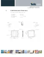
Page 12: ...11 07 22 Reproduction forbidden without Telit Communications S p A written authorization All Rights Reserved page 12 of 79 3 GL865 Mechanical Dimensions The GL865 overall dimensions are Length 24 4 mm...

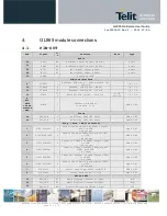
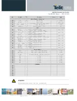
Page 13: ...SIM input See para 11 9 CMOS 2 8V Trace 44 RXD_AUX I Auxiliary UART RX Data CMOS 2 8V 45 TXD_AUX O Auxiliary UART TX Data CMOS 2 8V Prog Data HW Flow Control 1 C109 DCD GPO O Output for Data carrier d...

Page 14: ...8V 40 GPIO_03 DVI_TX I O GPIO03 Configurable GPIO Digital Audio Interface TX CMOS 2 8V 39 GPIO_04 TX Disable DVI_CLK I O GPIO04 Configurable GPIO TX Disable input Digital Audio Interface CLK CMOS 2 8V...

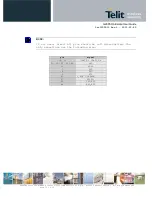
Page 15: ...cations S p A written authorization All Rights Reserved page 15 of 79 NOTE If not used almost all pins should be left disconnected The only exceptions are the following pins pin signal 38 37 VBATT VBA...

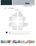
Page 16: ...22 Reproduction forbidden without Telit Communications S p A written authorization All Rights Reserved page 16 of 79 4 2 Pin Layout TOP VIEW NOTE The pin defined as NC RFU has to be considered RESERV...

Page 17: ...s the V_AUX PWRMON pin will be at the high logic level and the module can be consider fully operating When the power supply voltage is lower than 3 4V after 4000 m seconds the V_AUX PWRMON pin will be...

Page 18: ...ply the VBATT_PA and in second time apply VBATT never vice versa in this case can be damage the unit NOTE In order to avoid a back powering effect it is recommended to avoid having any HIGH logic leve...

Page 19: ...in OFF condition any power consumption is present Processor turn OFF disconnect the power supply only from the power pin VBATT the power pin VBATT_PA can be connected to power supply in this case a lo...

Page 20: ...MON must be monitored The device is powered off when PWRMON goes low NOTE In order to avoid a back powering effect it is recommended to avoid having any HIGH logic level signal applied to the digital...

Page 21: ...ked waiting for some network or SIM responses To unconditionally reboot the GL865 the pad RESET must be tied low for at least 200 milliseconds and then released NOTE Do not use any pull up resistor on...

Page 22: ...hart is detailed the proper restart procedure NOTE In order to avoid a back powering effect it is recommended to avoid having any HIGH logic level signal applied to the digital pins of the GL865 when...

Page 23: ...ll the following requirements POWER SUPPLY Nominal Supply Voltage 3 8 V Normal Operating Voltage Range 3 4 V 4 20 V Extended Operating Voltage Range 3 22 V 4 50 V NOTE The Operating Voltage Range MUST...

Page 24: ...mode GSM VOICE CALL GSM900 CSD PL5 230 DCS1800 CSD PL0 180 GPRS class 8 1TX GPRS Sending data mode GSM900 PL5 225 DCS1800 PL0 175 GPRS class 10 2TX GPRS Sending data mode GSM900 PL5 360 DCS1800 PL0 3...

Page 25: ...PC internal regulator output 12V input typically automotive Battery 6 3 1 1 5V input Source Power Supply Design Guidelines The desired output for the power supply is 3 8V hence there s not a big diffe...

Page 26: ...cause of its smaller inductor size and its faster transient response This allows the regulator to respond quickly to the current peaks absorption In any case the frequency and Switching design selecti...

Page 27: ...ts Reserved page 27 of 79 A protection diode should be inserted close to the power input in order to save the GL865 from power polarity inversion This can be the same diode as for spike protection An...

Page 28: ...E DON T USE any Ni Cd Ni MH and Pb battery types directly connected with GL865 Their use can lead to overvoltage on the GL865 and damage it USE ONLY Li Ion battery types A Bypass low ESR capacitor of...

Page 29: ...ch the device is requested to transmit by the network The average current consumption hence varies significantly Considering the very low current during idle especially if Power Saving function is ena...

Page 30: ...ally to avoid the voltage drops on the power line at the current peaks frequency of 216 Hz that will reflect on all the components connected to that supply introducing the noise floor at the burst bas...

Page 31: ...2011 07 22 Reproduction forbidden without Telit Communications S p A written authorization All Rights Reserved page 31 of 79 The power supply input cables should be kept separate from noise sensitive...

Page 32: ...d 1850 1990MHz PCS1900 band 880 960 MHz GSM900 band 1710 1885MHz MHz DCS1800 band Gain 1 4dBi GSM900 and 3dBi DCS1800 1 4dBi GSM850 and 3dBi PCS1900 1 4dBi GSM900 and 3dBi DCS1800 Impedance 50 Ohm 50...

Page 33: ...at least one layer of the PCB used only for the Ground plane If possible use this layer as reference Ground plane for the transmission line It is wise to surround on both sides the PCB transmission l...

Page 34: ...sible A Grounded Coplanar Waveguide G CPW line has been chosen since this kind of transmission line ensures good impedance control and can be implemented in an outer PCB layer as needed in this case A...

Page 35: ...calibration has been used in this measurement session A calibrated coaxial cable has been soldered at the pad corresponding to GL865 RF output a SMA connector has been soldered to the board in order...

Page 36: ...without Telit Communications S p A written authorization All Rights Reserved page 36 of 79 Line input impedance in Smith Chart format once the line has been terminated to 50 load is shown in the foll...

Page 37: ...unications S p A written authorization All Rights Reserved page 37 of 79 7 4 GSM Antenna Installation Guidelines Install the antenna in a place covered by the GSM signal Antenna shall not be installed...

Page 38: ...unctional Parameter Min Max Input level on any digital pin CMOS 2 8 when on 0 3V 3 1V Input level on any digital pin CMOS 1 8 when on 0 3V 2 1V Input voltage on analog pins when on 0 3V 3 0 V Operatin...

Page 39: ...ormally shutting down the device but only as an emergency exit in the rare case the device remains stuck waiting for some network response The RESET is internally controlled on start up to achieve alw...

Page 40: ...GL865 Hardware User Guide 1vv0300910 Rev 1 2011 07 22 Reproduction forbidden without Telit Communications S p A written authorization All Rights Reserved page 40 of 79...

Page 41: ...ceive Transmit microcontroller UART 5V or other voltages different from 2 8V Depending from the type of serial port on the OEM hardware a level translator circuit may be needed to make the system work...

Page 42: ...round 6 DSR dsr_uart 3 Data Set Ready Output from the GL865 that indicates the module is ready 7 RTS rts_uart 5 Request to Send Input to the GL865 that controls the Hardware flow control 8 CTS cts_uar...

Page 43: ...signal voltage must be less than 0V and hence some sort of level translation is always required The simplest way to translate the levels and invert the signal is by using a single chip level translat...

Page 44: ...GL865 Hardware User Guide 1vv0300910 Rev 1 2011 07 22 Reproduction forbidden without Telit Communications S p A written authorization All Rights Reserved page 44 of 79...

Page 45: ...example of level translation circuitry of this kind is The example is done with a MAXIM MAX3237 Transceiver that could accept supply voltages of 3V DC Not exceeded with supply voltage higher then 3 1V...

Page 46: ...e the compliance with RS232 5V is possible Another level adapting method could be done using a standard RS232 Transceiver MAX3237EAI adding some resistors to adapt the levels on the GL865 Input lines...

Page 47: ...vels of the two set of signals As for the RS232 translation there are a multitude of single chip translators For example a possible translator circuit for a 5V TRANSMITTER RECEIVER can be TIP Note tha...

Page 48: ...lled up with 47K In case of reprogramming of the module has to be considered the use of the RESET line to start correctly the activity The preferable configuration is having an external supply for the...

Page 49: ...source The bias for the microphone is already provided by the product so the connection can be done in both following ways For more information refer to Telit document 80000NT10007a Audio Settings App...

Page 50: ...following connections can be done Place a 1Kohm resistor to ground on the negative input in order to get balanced the input than connect the source via 1uF capacitor so the DC current is blocked Since...

Page 51: ...udspeaker with electrical impedance not lower than 8Ohm TIP in order to get the maximum audio level at a given output voltage level dBspl Vrms the following breaking through procedure can be used Have...

Page 52: ...0 290mVrms AT HFMICG 1 6dB 145mVrms AT HFMICG 2 12dB 72mVrms AT HFMICG 3 18dB 36mVrms AT HFMICG 4 24dB 18mVrms AT HFMICG 5 30dB 9mVrms AT HFMICG 6 36dB 4 5mVrms AT HFMICG 7 42dB 2 25mVrms 0 dBm0 in th...

Page 53: ...nt 2dB per step volume steps 0 10 in default condition AT CLVL 10 AT HFRECG 0 TIP We suggest driving the load differentially this kills all the common mode noises click and pop for example the output...

Page 54: ...GL865 Hardware User Guide 1vv0300910 Rev 1 2011 07 22 Reproduction forbidden without Telit Communications S p A written authorization All Rights Reserved page 54 of 79...

Page 55: ...ollowing table shows the available GPIO on the GL865 Pin Signal I O Function Type Input output current Default State ON_OFF state State during Reset Note 42 GPIO_01 I O Configurable GPIO CMOS 2 8V 1uA...

Page 56: ...ate function C107 DSR 4 GPI_E I Configurable GPI CMOS 2 8V 1uA 1mA INPUT 0 0 Alternate function C108 DTR 5 GPI_F I Configurable GPI CMOS 2 8V 1uA 1mA INPUT 0 0 Alternate function C105 RTS 6 GPO_D O Co...

Page 57: ...llector transistor with a 47K pull up to 2 8V NOTE In order to avoid a back powering effect it is recommended to avoid having any HIGH logic level signal applied to the digital pins of the GL865 when...

Page 58: ...n 11 5 Using the Alarm Output GPIO6 The GPIO6 pad when configured as Alarm Output is controlled by the GL865 module and will rise when the alarm starts and fall after the issue of a dedicated AT comma...

Page 59: ...4148 C1 33pF V buzzer GPIO7 NOTE To correctly drive a buzzer a driver must be provided its characteristics depend on the Buzzer and for them refer to your buzzer vendor 11 7 Magnetic Buzzer Concepts 1...

Page 60: ...drive signal Thus the sound is produced relative to the frequency applied Diaphragm movement 11 7 1 Frequency Behaviour The frequency behaviour represents the effectiveness of the reproduction of the...

Page 61: ...rcuitry does not support these peak values the SPL will never reach the declared level or the oscillations will stop 11 8 STAT LED Indication of network service availability The STAT_LED pin status sh...

Page 62: ...blinking Period 3s Ton 0 3s Registered full service Permanently on a call is active NOTE Don t use the STAT LED function if the GPIO 8 function is enabled and vice versa A schematic example could be...

Page 63: ...reports the selected I O pin in the format SIMINCFG 1 AT SIMINCFG Test command reports supported range of values for parameters in the format SIMINCFG 0 8 0 disabled Use the AT command AT SIMDET 2 to...

Page 64: ...k supply which is separate from the rest of the digital part allowing having only RTC going on when all the other parts of the device are off To this power output a backup battery can be added in orde...

Page 65: ...5 The on board DAC is a 10 bit converter able to generate a analogue value based a specific input in the range from 0 up to 1023 However an external low pass filter is necessary Min Max Units Voltage...

Page 66: ...is available to use the DAC function The command is AT DAC enable value value scale factor of the integrated output voltage 0 1023 10 bit precision it must be present if enable 1 Refer to SW User Guid...

Page 67: ...input store and convert it into 11 bit word Min Max Units Input Voltage range 0 2 Volt AD conversion 11 bits Resolution 1 mV The GL865 module provides 2 Analog to Digital Converters The input lines a...

Page 68: ...ecommend to foreseen test pads on the host PCB in order to check the connection between the GL865 itself and the application and to test the performance of the module connecting it with an external co...

Page 69: ...itten authorization All Rights Reserved page 69 of 79 13 Mounting the GL865 on your Board 13 1 General The GL865 modules have been designed in order to be compliant with a standard lead free SMT proce...

Page 70: ...ication In order to easily rework the GE865 is suggested to consider on the application a 1 5 mm placement inhibit area around the module It is also suggested as common rule for an SMT component to av...

Page 71: ...s S p A written authorization All Rights Reserved page 71 of 79 13 4 Solder paste Lead free Solder paste Sn Ag Cu We recommend to use only no clean solder paste in order to avoid the cleaning of the m...

Page 72: ...ature Max Tsmax Time min to max ts 150 C 200 C 60 180 seconds Tsmax to TL Ramp up Rate 3 C second max Time maintained above Temperature TL Time tL 217 C 60 150 seconds Peak Temperature Tp 245 0 5 C Ti...

Page 73: ...age 73 of 79 14 Packing system The GL865 modules are packaged on trays of 20 pieces each This is especially suitable for the GL865 according to SMT processes for pick place movement requirements NOTE...

Page 74: ...ut Telit Communications S p A written authorization All Rights Reserved page 74 of 79 14 1 Moisture sensibility The level of moisture sensibility of GL865 is 3 in according with standard IPC JEDEC J S...

Page 75: ...onformance to the Telit installation manuals no further evaluation under Article 3 2 of the R TTE Directive and do not require further involvement of a R TTE Directive Notified Body for the final prod...

Page 76: ...ing has to be conforming to the security and fire prevention regulations The product has to be handled with care avoiding any contact with the pins because electrostatic discharges may damage the prod...

Page 77: ...y Requirements This device complies with Part 15 of the FCC Rules Operation is subject to the following two conditions 1 this device may not cause harmful interference and 2 this device must accept an...

Page 78: ...lations this radio transmitter may only operate using an antenna of a type and maximum or lesser gain approved for the transmitter by Industry Canada To reduce potential radio interference to other us...

Page 79: ...ed are strictly prohibited for use with this device Le GL865 QUAD a t con u pour se conformer aux exigences de s curit pour l exposition aux ondes radio SAR en conformit avec RSS 102 S il vous pla t s...

Reviews: