


GL865 Hardware User Guide
1vv0300910 Rev.1 – 2011-07-22
Reproduction forbidden without Telit Communications S.p.A. written authorization - All Rights Reserved
page 32 of 79
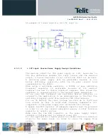
7.
Antenna
The antenna connection and board layout design are the most
important aspect in the full product design as they strongly
affect the product overall performances, hence read carefully
and follow the requirements and the guidelines for a proper
design.
7.1.
GSM Antenna Requirements
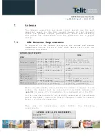
As suggested on the Product Description the antenna and antenna
transmission line on PCB for a Telit GL865 device shall fulfil the
following requirements:
ANTENNA REQUIREMENTS
QUAD
DUAL
Frequency range
824-894 MHz GSM850 band
880-960 MHz GSM900 band
1710-1885MHz DCS1800 band
1850-1990MHz PCS1900 band
880-960 MHz GSM900 band
1710-1885MHz MHz DCS1800
band
Gain
1.4dBi @ GSM900 and 3dBi @
DCS1800
1.4dBi @ GSM850 and 3dBi @
PCS1900
1.4dBi @ GSM900 and 3dBi @
DCS1800
Impedance
50 Ohm
50 Ohm
Input power
> 2 W
> 2 W
VSWR absolute
max
≤
10:1 (limit to avoid
permanent damage)
≤
10:1 (limit to avoid
permanent damage)
VSWR recommended
≤
2:1 (limit to fulfil all
regulatory requirements)
≤
2:1 (limit to fulfil all
regulatory requirements)
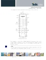
When using the GL865, since there's no antenna connector on the
module, the antenna must be connected to the GL865 antenna pad
(pin 34) by means of a transmission line implemented on the PCB.
In the case the antenna is not directly connected at the antenna
pad of the GL865, then a PCB line is needed in order to connect
with it or with its connector.
This
line
of
transmission
shall
fulfill
the
following
requirements:
ANTENNA LINE ON PCB REQUIREMENTS
Characteristic
Impedance
50 Ohm
Max Attenuation
0,3 dB


