


GL865 Hardware User Guide
1vv0300910 Rev.1 – 2011-07-22
Reproduction forbidden without Telit Communications S.p.A. written authorization - All Rights Reserved
page 52 of 79
10.1.
Electrical Characteristics
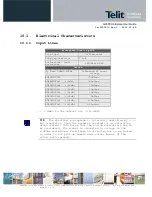
10.1.1.
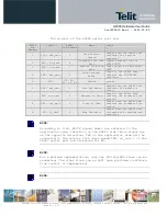
Input Lines
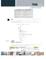
Microphone/Line-in path
Line Type
Differential
Coupling capacitor
≥
1
µ
F
Differential input
resistance
1k
Ω
/2k
Ω
/2.2k
Ω
Levels
To have 0dBm0 @1KHz
(*)
Differential input
voltage
AT#HFMICG=0
290mVrms
AT#HFMICG=1
(+6dB)
145mVrms
AT#HFMICG=2
(+12dB)
72mVrms
AT#HFMICG=3
(+18dB)
36mVrms
AT#HFMICG=4
(+24dB)
18mVrms
AT#HFMICG=5
(+30dB)
9mVrms
AT#HFMICG=6
(+36dB)
4.5mVrms
AT#HFMICG=7
(+42dB)
2.25mVrms
(*)
0 dBm0 in the network are -3.14 dBfs
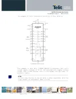
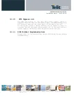
TIP: The Electrect microphone is internally amplified by a J-
Fet transistor, thus the sound is carried out as saturation
drain current; this means that the norton equivalence has to
be considered. The signal is converted to voltage on the
2.2KOhm resistance, from there on circuitry has to be routed
in order to not pick up common mode noise; beware of the
return path (ground).


