background image


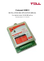
Compact GSM II 


INSTALLATION AND APPLICATION MANUAL


For module version V2.26.2066 and up 


Document version: 1.8  10.03.2014 

Summary of Contents for Compact GSM 2

Page 1: ...Compact GSM II INSTALLATION AND APPLICATION MANUAL For module version V2 26 2066 and up Document version 1 8 10 03 2014 ...

Page 2: ... commands 13 2 5 Control of outputs by SMS 16 2 6 Status query 16 2 7 Recording voice messages 17 2 8 Call and SMS restriction 17 2 9 Functions of the program button 17 2 10 Restoring factory default settings 17 2 11 Volume adjusting application 18 3 Module overview 19 4 LED signals 19 5 Wiring diagram 20 6 Installation guide 21 6 1 Mounting 21 6 2 Putting into operation 21 7 Technical details 21 ...

Page 3: ...odem connection using software or by SMS 1 2 Features 4 user phone numbers for GSM calls and SMS sending Forwards incoming SMS messages to the first user phone number 1 monitoring station phone number for reporting 2 NO NC inputs 2 NO relay outputs Possibility to connect temperature sensor 2 Settings The module can be configured using its programming software through USB or modem connection or by ...

Page 4: ...ns become available on the Settings page and module status information on the Status page Configure the settings then load to the module using Write button 2 2 Configuring using the software through modem connection To establish modem connection it is necessary to have GSM data call CSD service enabled on both SIM cards the one placed in the modem and the one in the module Start the programming so...

Page 5: ...accepting the call confirms the alarm event automatically by pressing key on the phone stops reporting to the further phone numbers ack Stop the user must confirm the event by pressing key on the phone otherwise the module recalls the number until the user confirms the alarm event Pressing key on the phone stops reporting to the further phone numbers ack upon call reject the alarm event can be con...

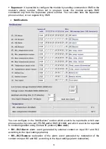
Page 6: ...an configure in the Notifications section which event to be reported to which user phone number by voice call T1 T4 and or SMS S1 S4 and which event to be reported to monitoring station using Contact ID protocol Mon stat IN1 IN2 Alarm alarm event generated by external contact on input IN1 and IN2 according to the input settings alarms IN1 IN2 Restore restoration of the alarm event generated by res...

Page 7: ...f the module s supply voltage drops below the configured low battery voltage threshold for at least 30 seconds Battery restore this event is generated if the module s supply voltage restores above the configured voltage restore threshold for at least 30 seconds Test report the periodic test report to be sent by the configured frequency The test report sending time of day can be set by pressing Sen...

Page 8: ...ts to report that event This only refers to that specific event calls and SMS messages initiated by other new events will continue to be reported Attention Each event is reported to user phone numbers by separate call SMS If a power loss occurs the module stores all events in progress which are still unreported and restarts reporting these events when the supply voltage restores Test report freque...

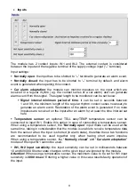
Page 9: ...if no more impulses are received on the input after an alarm for at least the time interval set here Temperature sensor an optional TELL easyTEMP temperature sensor can be connected to input IN1 Enable this option in case of connecting a temperature sensor When using a temperature sensor the Normally open input mode can be used at the same time taking in consideration that the module is unable to ...

Page 10: ... communication or GSM network failure and the relay is activated at restart the relay will deactivate for 1 second then will return to the activated state Timed it can be set in seconds between 1 and 9999 how long the relay should remain activated after an activation event occurs If no further activation event occurs the relay will deactivate automatically when the time expires If a new activation...

Page 11: ... relay is controlled from unknown phone number On temperature event it is possible to configure the relay to be activated or deactivated between configured min max temperature thresholds The relay control is done when the measured temperature increases above respectively drops below the configured threshold with 1ºC for at least 30 seconds The temperature event that controls the relay is independe...

Page 12: ...he type hardware and firmware version of the connected module System timer the time elapsed from powering up the module GSM status the actual GSM signal strength the lowest signal measured and the time elapsed from connecting to the GSM network Power supply The actual value of the supply voltage in millivolts and the lowest voltage measured from powering up the module Temperature the actual temper...

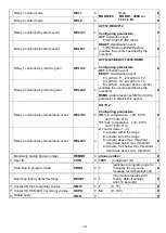
Page 13: ...ble disable 1 0 IN1 Alarm IN1A CID1130 T1011 S1001 C1 SMS text Configuring parameters CID 4 digit Contact ID code T T1 T2 T3 T4 enable disable 1 0 S S1 S2 S3 S4 enable disable 1 0 C report to mon stat enable disable 1 0 SMS message text any parameter value which should not be modified can be omitted IN2 Alarm IN2A IN1 Restore IN1R IN2 Restore IN2R Min temperature alarm TLA Min temperature restore ...

Page 14: ...e this option Relay 2 controlled by incoming call REL2C2 Relay 1 controlled by temperature event REL1C3 XX YY Z Configuring parameters XX min temperature 20 56 ºC but YY XX 4ºC YY max temperature 16 60 ºC but YY XX 4ºC Z control mode 1 4 1 activate within the range 2 activate out of the range 3 activate above max threshold deactivate below min threshold 4 activate min below min threshold deactivat...

Page 15: ...phone numbers 1 and 2 enabled SMS sending to user phone number 3 disabled reporting to monitoring station and Panic alarm SMS message IN2A CID1120 T1100 S0010 C0 SMS Panic alarm Configuring control of relay 1 by temperature event with 20ºC minimum and 26ºC maximum temperature threshold using the third control mode activate the relay above the maximum temperature threshold and deactivate below the ...

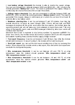
Page 16: ...mmands Attention Control by SMS of the relay output is restricted if the control mode of the given output is configured to temperature event This option disables control by SMS 2 6 Status query There is possibility for status query in SMS The module accepts the status request command only from the configured 4 user phone numbers and from the superuser phone number To request module status in SMS s...

Page 17: ...oice message of IN2 Alarm event erasing the voice messages recorded for IN1 Alarm and IN2 Alarm events restoring the siren tone When recording voice messages speak loud and close to the phone s microphone 2 8 Call and SMS restriction The module has built in call and SMS restriction function which allows 50 outgoing calls and sending 50 SMS messages per day 2 9 Functions of the program button The p...

Page 18: ...ecome available Read the actual settings from the module by pressing Read from module button CID setting adjusts the volume of the communication to monitoring station Mic volume microphone volume outgoing Contact ID Spk volume speaker volume incoming HSK ACK User setting adjusts the volume of the voice communication to from user phone numbers Mic volume microphone volume outgoing voice message sir...

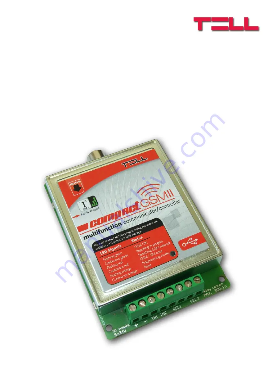
Page 19: ... GSM network Continuous red GSM SIM error Continuous green Reporting through GSM in progress Flashing green GSM network is available idle Green performs a determined number of blinks after pressing the program button GSM signal query Flashing orange Program mode ...

Page 20: ...20 5 Wiring diagram For normally open and normally closed setting REL1 and REL2 outputs are normally open Connecting the temperature sensor ...

Page 21: ...alls on the SIM card placed into the module Enable caller ID sending and caller identification service on the SIM card at the GSM service provider Place the SIM card into the SIM slot according to the sticker on the module If you want to remove the SIM card just push the card again Check the antenna to be fixed properly to the Compact GSM II module Check the wires to be connected as instructed by ...

Reviews: