7
2. Mounting the module and putting into operation
2.1 Module version
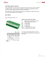
The Pager 7 has two module version. The first has 4 contact inputs (IN1...IN4) and 2 relay
outputs (OUT1, OUT2)
– Pager 7 Z4, while the second one has 6 inputs (IN1...IN6) and 1 output
(OUT1)
– Pager 7 Z6.
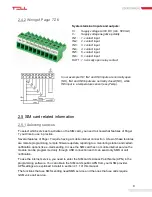
For connecting the module correctly, wiring diagrams of the corresponding version must be
used!
2.2 Inputs and outputs
Attention!
Do NOT connect the module’s terminals directly or indirectly to the protective
ground, because this may damage the module!
2.2.1 Connecting inputs
Both the inputs of Pager 7 and the event-actions for their activation can be customized, so the
NO or NC wiring can be also used in accordance with the selected usage.
The normally closed and normally open contacts are considered between the selected input
(eg.: IN1) and the negative „V”-terminal of the supply voltage and need to be connected
accordingly.
For the proper operation of inputs, it is essential to specify the type of inputs (NO or NC) and
enable them in the programming software. These settings are explained in detail in section 4.2
of this manual.
2.2.2 Connecting temperature sensor
Each input of Pager 7 is capable of handling temperature sensor (easyTemp). Connect the
signal output of the temperature sensor to the selected input of the module and set the input
type to temperature sensor in the programming software. This setting is explained in detail in
section 4.2 of this manual.
2.2.3 Connecting outputs
The outputs of Pager 7 are normally opened (NO) so wire them accordingly to process the given
task. The normally open (N.O.) output provides open contact by default and closed contact upon
control. The maximum relay output load is 1A at 24V AC/DC voltage.


