Section 11 TECHNICAL INFORMATION
198
PHILOSOPHY
In the past few years, the nature of broadcast engineering has changed considerably. At
many stations, the engineering staff has been reduced in size and new responsibilities
have been added. At the same time, equipment has gotten more complicated and
specialized. Thus, many practitioners of the broadcast electronic arts are forced to
become “systems” engineers, emphasizing equipment application rather than
component- level troubleshooting.
This is probably a positive development, since it really would be impossible for a station
engineer to fully understand the internal nuances of all the wonderful new high- tech
stuff that is now available to improve station operations! Also, as equipment becomes
more sophisticated and specialized, stocking spare parts for every eventuality has
become difficult.
Thus, we at Telos don’t really expect that much component- level troubleshooting will
occur. To support you when you need help, we keep spare boards available for fast
overnight shipping. In most cases, we will swap boards with you at no cost. We do not
charge for most repairs.
However, despite the comments above, we do provide schematics and component level
troubleshooting information in case you have the need or desire to tackle a repair (or
modification) yourself. Another reason we provide the information is to satisfy your
curiosity. If you are like us, you probably just have to know what’s happening inside that
fancy box.
DSP CARDS, CONFIGURATION, MODES
This section contains detailed information on the DSP card configurations and resulting
operating mode capability. It describes the usage of the various DSP chips along with
the digital audio signal flow. It is a good starting point to acquire understanding the
design of the unit.
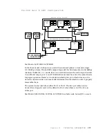
The Zephyr may have one or two DSP cards installed. The first, leftmost socket position
must always have a DSP card, and this card must be the “primary” type – all three DSP
chips must be present on the Printed Circuit Board. The rightmost socket position may
have a “secondary” DSP card installed – only two DSP chips are present on this module.
DSP56002
U2
DSP56002
U3
U1
DSP32C
A “ primary” (Mono) DSP card. It has all three
DSP chips present, and must go into the leftmost
socket within the Zephyr.
Summary of Contents for Zephyr
Page 13: ...Table of Contents 13 SECTION 1 QUICK RESULTS ...
Page 26: ...Section 2 INTRODUCTION 26 This page intentially left blank ...
Page 27: ...Section 2 INTRODUCTION 27 SECTION 2 INTRODUCTION ...
Page 38: ...Section 2 INTRODUCTION 38 This page intentionally left blank ...
Page 39: ...39 SECTION 3 ZEPHYR AT A GLANCE ...
Page 52: ...Section 4 INSTALLATION BASIC OPERATION 52 This page intentionally left blank ...
Page 53: ...Section 4 INSTALLATION BASIC OP 53 SECTION 4 INSTALLATION BASIC OPERATION ...
Page 84: ...Section 4 INSTALLATION BASIC OPERATION 84 ...
Page 85: ...Section 5 ISDN 85 SECTION 5 ISDN ...
Page 105: ...Section 6 NON ISDN NETWORKS 105 SECTION 7 AUDIO CODING ...
Page 118: ...Section 7 AUDIO CODING PRINCIPLES 118 This page intentionally left blank ...
Page 119: ...Section 8 DETAILED MENU REFERENCE 119 SECTION 8 DETAILED MENU REFERENCE ...
Page 157: ...Section 9 REMOTE CONTROL 157 SECTION 9 REMOTE CONTROL ...
Page 176: ...Section 9 REMOTE CONTROL 176 This page intentionally left blank ...
Page 177: ...Section 10 ADVANCED PROBLEM SOLVING 177 SECTION 10 ADVANCED PROBLEM SOLVING ...
Page 196: ...Section 10 ADVANCED PROBLEM SOLVING 196 This page intentionally left blank ...
Page 197: ...Section 11 TECHNICAL INFORMATION 197 SECTION 11 DETAILED TECHNICAL INFORMATION ...
Page 219: ...Section 12 SCHEMATICS 219 SECTION 12 SCHEMATICS ...
Page 221: ...Section 13 MANUFACTURER S DATA SHEETS 221 SECTION 13 MANUFACTURER S DATA SHEETS ...
Page 223: ...Section 14 SPECIFICATIONS WARRANTY 223 SECTION 14 SPECIFICATIONS AND WARRANTY ...
Page 228: ...228 This page intentionally left blank ...
Page 229: ...Section 15 APPENDICES 229 SECTION 15 APPENDICES ...


