background image

Page 9 


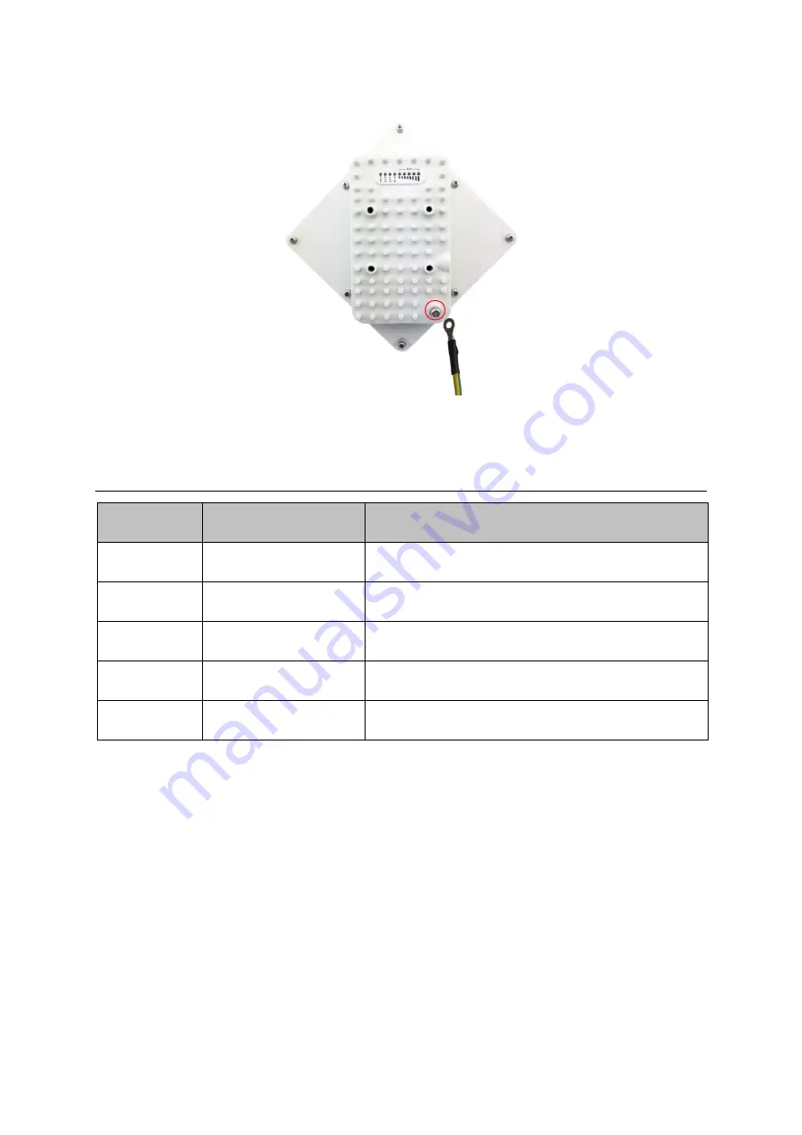
Connect one of a grounding cable to the grounding screw and firmly tighten the grounding 
screw. Connect the opposite end of the grounding cable to a good ground(earth) connection. 

2


LED Display  


LED Indicator 

Function 

Description 

PWR 

Power Indicator  

Green Color – Device is powered on 

RUN 

System Run Indicator 

Fast Blinking – Device is rebooting 
Slow Blinking – Device is in normal operation    

LAN  

LAN port status 

Solid Green –  LAN port is up 
Blinking Green – LAN data activity in progress 

SIM 

SIM Card Indicator 

Light is on – SIM Card Error 

RF (5 LEDs) 

RF Signal Strength 

5 level signal strengths indication by 5 green LEDs 


RF Signal Adjustment 

After the CPE outdoor unit has installed, the direction of antenna’s azimuth and pitch angle 

needs to adjust for the best signal strength. In near line of sight condition, the CPE will have 

the best signal when the antenna is directly pointing the base station. 

User can adjust the holder to change the direction and angle of the antenna while observing 

the RF LED on the outdoor unit which indicates the signal strength. 

Summary of Contents for CPE8100

Page 1: ...Page 1 CPE8100 Outdoor CPE Quick installation guide V1 0...

Page 2: ...ormance Declaration Marking by the above symbol indicates compliance with the Essential Requirements of the R TTE Directive of the European Union 1999 5 EC This equipment can meet the following confor...

Page 3: ...ould void the user s authority to operate the equipment FCC Radiation Exposure Statement This equipment complies with FCC radiation exposure limits set forth for an uncontrolled environment This equip...

Page 4: ...5 2 GETTING STARTED 5 DEVICE LOGIC CONNECTION 6 INSTALLING OUTDOOR UNIT ODU POLE MOUNT 7 INSTALLING OUTDOOR UNIT ODU WALL MOUNT 7 GROUNDING 8 2 LED DISPLAY 9 RF SIGNAL ADJUSTMENT 9 3 MANAGING CPE DEV...

Page 5: ...supply ODU Power 12 Watts Dimensions 203 mm L 203 mm W 76 mm D Weight 3 Kg 2 Getting Started 1 Packing list Upon receiving the product please unpack the product package carefully Each product is shipp...

Page 6: ...a 48V PoE integrated DC power supply adapter The power adapters can operate in 100 240V AC range and therefore can be used in different country Once the device is powered up the user should wait for...

Page 7: ...Installing Outdoor Unit ODU Pole Mount Installing Outdoor Unit ODU Wall Mount Note The wall screws and screw anchors are not part of the package Recommended screw size minimum 50mm length and 6 8mm di...

Page 8: ...t is highly recommended to ensure that the outdoor unit and the antenna mast are grounded and suitable lightning protection devices are used so as to provide protection against voltage surges and stat...

Page 9: ...port is up Blinking Green LAN data activity in progress SIM SIM Card Indicator Light is on SIM Card Error RF 5 LEDs RF Signal Strength 5 level signal strengths indication by 5 green LEDs RF Signal Adj...

Page 10: ...PC connected to device LAN port The user should ensure that the connected PC have acquired IP address via DHCP from the device After IP connectivity is established between the PC and CPE device the u...

Page 11: ...connect to the CPE Re plug the PC Ethernet cable and check if the PC LAN connection is up or showing activity Check if the PoE power adapter LED is on If it is not check the power cord and make sure...

Page 12: ...check the Interface Info page You may want to perform a factory reset and see if the problem is being corrected You can do this by log into the WEB GUI using admin password and perform restore the un...

Reviews: