background image

TEM 

A07EXXXX – 1 Unit Transmitters 

Page 82


Parts Placement

ST

AF

33336

02.09.14

13M31810

Current Sensor

G3181-1


13M31810 Part list 

Summary of Contents for A07E0011

Page 1: ...mitters A07E XXXX Watt 0011 10 0021 20 0031 30 0051 50 0101 100 0201 200 0251 250 0301 300 0401 400 0501 500 Operation Manual 2014 2027 Copyright by Telecomunicazioni Elettroniche Milano Srl Via Copernico 11 20082 Milano Italy All rights reserved All specifications characteristics and circuit descriptions set forth in this manual are subject to change without notice ...

Page 2: ... Pages 19 20 Antonio Fiordelisi 03 25 02 2015 Rev page 21 34 35 Antonio Fiordelisi 04 02 03 2015 Pag 08 Antonio Fiordelisi 05 22 05 2015 Pag 15 16 24 Antonio Fiordelisi 06 21 11 2016 Pag 14 15 16 25 36 Antonio Fiordelisi 07 02 06 2017 Pag 16 17 18 84 85 86 87 88 Antonio Fiordelisi 08 01 02 2018 Pag 21 Antonio Fiordelisi 09 25 02 2019 Pag 2 18 84 85 86 87 91 92 93 116 121 Antonio Fiordelisi 10 19 0...

Page 3: ...precautions 12 3 9 Electrostatic precautions 12 3 10 Waste electrical and electronic equipment WEEE 13 4 ELECTRICAL SPECIFICATION 14 4 1 FREQUENCY POWER 14 4 3 MODULATION CAPABILITY 15 4 4 CHARACTERISTICS IN MPX 15 4 5 CHARACTERISTICS IN MONO 15 4 6 CHARACTERISTICS IN STEREO 16 4 7 SCA Ext RDS CHARACTERISTICS 16 4 8 REMOTE CONTROL 16 4 9 POWER SUPPLY AND TEMPERATURE RANGE 17 4 10 MECHANICAL SPECIF...

Page 4: ...ply 23 8 4 Ground loops 23 8 5 Rear Panel Description 24 8 6 Audio Inputs Connectors Description 25 8 7 Audio Alarm Detector Automatic Audio Changeover Description 25 8 8 Transmitter power up 26 8 9 Front Panel Description 26 8 10 Transmitter settings referred A07E0501 model 27 9 DIAGRAMS AND PART LIST 40 ...

Page 5: ... THE TRANSMITTER ANY TRANSMITTER SERVICING REPAIRING OR CHECKING OPERATION REQUIRING THE OPENING OF THE TOP OR BOTTOM COVER MUST BE PERFORMED AFTER THE MAINS SUPPLY DISCONNECTION WITHOUT REMOVING THE EARTH CONNECTION WHICH THE EFFICIENCY MUST BE VERIFIED THE CABLE MUST BE IN GOOD CONDITIONS AND WELL CONNECTED STAFF OPERATING UPON THE TRANSMITTER SYSTEM MUST NOT BE TIRED AFTER HEAVY WORKS OR CARRYI...

Page 6: ...SERVE SAFETY INSTRUCTIONS The staff in charge besides being technically qualified must have a practice of the first aid in case of emergency or accident reanimation heart massage mouth to mouth respiration etc Before going on with the operations to be performed it is necessary to know the position of the general electric switch and the one of the extinguishers which are to be used very quickly if ...

Page 7: ... electrical shock is removed when the power is off Charged capacitors can retain dangerous voltages for a long time after power is turned off These capacitors should be discharged trough a suitable resistor before any circuit points are touched Don t take chances Be fully trained TEM Italia equipment should be operated and maintained by fully qualified personnel Do not service alone and do not per...

Page 8: ...nded through the grounding conductor of the power cord To avoid electrical shock plug the power cord into a properly wired socket before connecting to the product input or output terminals Upon loss of the protective ground connection all accessible conductive parts including parts that may appear to be insulating can render an electric shock To avoid fire hazard use only the fuse of correct type ...

Page 9: ...ircuit be modified without specific approval of the appropriate authority in each case When connecting any instrument wattmeter spectrum analyzer etc to a high frequency output use the appropriate attenuator or dummy load to protect the final amplifiers and the instrument input When inserting or removing printed circuit boards PCBs cable connectors or fuses always turn off power to the affected po...

Page 10: ...e of voltage These earthing connections shall be very short compared with the wave lenght Capacitors which are connected to a circuir isolated from its supply shall be discharged and have their terminals permanently short circuited and the casing earthed during the whole period of the work The electrical charge retained by electrical machinery when stopped may in certain cases be sufficient to cau...

Page 11: ...ly avoid touching him or his clothing until free of power 3 7 Emergency resuscitation technique Step 1 Check the victim for unresponsiveness If there is no response immediately call for medical assistance and then return to the person Step 2 Position the person flat on their back Kneel by their side and place one hand on the forehead and the other under the chin Tilt the head back and lift the chi...

Page 12: ... surfaces to be in contact with each other such as areas between the fingers or toes the ears and the side of the head the undersurface of the arm and the chest wall the folds of the groin and similar places Transport to a medical facility 3 8 Electric safety precautions All the parts making up the equipment have got danger identification tags with a yellow background to highlight the parts danger...

Page 13: ...le cord To be connected to the elastic wrist band and the special plug on the shelf highlighted with the ESD warning label 3 10 Waste electrical and electronic equipment WEEE The purpose of the DIRECTIVE 2002 96 EC OF THE EUROPEAN PARLIAMENT AND OF THE COUNCIL of 27 January 2003 on waste electrical and electronic equipment WEEE is as first priority the prevention of waste electrical and electronic...

Page 14: ...l GSM TCP IP RS232 RS485 Frequency stability 500Hz year Frequency generation PLL synthesizer Modulation type direct VCO frequency modulation Nominal frequency deviation 75KHz RF output power 0 to 10 20 50 100 200 250 300 400 500W Power resolution setting 1 5W Power control stability 0 2dB Reverse output power control limit 1 to 30W Harmonics emission 70dBc Spurious emission 95dBc Carrier reduction...

Page 15: ...X Signal input MPX Unbalanced Input impedance 600 or 10k Input level 0 6 12 dBm or Variable input level capability Audio frequency response 50Hz to 57KHz 0 5dB Total Harmonic Distortion THD 0 02 Signal to noise referred at deviation of 75KHz 80dB 4 5 CHARACTERISTICS IN MONO Signal input Left or Right Input impedance 600 balanced or 10k Unbalance rejection 40dB Input level 0 6 12 dBm or Variable in...

Page 16: ...Total Harmonic Distortion THD 0 1 Signal to noise referred at deviation of 75KHz 77dB Suppression of 38KHz 70dB Spurious suppression outside band in according to ETS 300 384 Pilot reference for RDS encoder 19 KHz out 1Vpp 4 7 SCA Ext RDS CHARACTERISTICS Input SCA1 BNC unbalanced Input impedance 10K Frequency response 50KHz to 100KHz 0 2dB Modulation capability 0 to 10 4 8 REMOTE CONTROL AUX I O on...

Page 17: ...W Model Line Power 175VA 100W RF Output Power 300W Model Line Power 450VA 300W RF Output Power 500W Model Line Power 710VA 500W RF Output Power Nominal temperature range 5 to 45 C Operating temperature range 10 to 50 C Storage temperature range 40 to 50 C 4 10 MECHANICAL SPECIFICATION 1 unit rack 19 485x44 4x545mm 10 20 50W model Weight 6 0Kg 100W model Weight 7 5Kg 300W model Weight 8 0Kg 500W mo...

Page 18: ...S7524 Current Meter Sensor Module only for 500W model 13M31810 Universal Current Meter Sensor Module for all 1 Unit Rack TX models 13M32110 4 12 OPTIONS Option A Internal Stereo generator Module 44C01180 Option B Internal RDS Encoder 13M7MINIRDS Option C AES EBU Digital Input Interface 13MAESEBU0 Option D Automatic Frequency Deviation Control Card 13M5804A Option E GSM by SMS Remote Control 13KGSM...

Page 19: ...0 W 20 W 10 W Versione software L 27 XX La potenza di uscita di ogni singolo apparato è certificata dalla presenza di uno dei suddetti codici sull etichetta apposta sull apparato stesso e sulla presente Dichiarazione di Conformità L oggetto della dichiarazione è conforme alla pertinente normativa di armonizzazione dell Unione Direttiva 2014 53 UE Norma applicata Data Emesso da EN 302 018 V2 1 1 EN...

Page 20: ...mware L 27 XX The output power of each individual is certified by the presence of one of the aforementioned codes on the label affixed to the apparatus itself and to this Declaration of Conformity The object of the declaration described above is in conformity with the relevant Union harmonisation legislation Directive 2014 53 UE RED Standard Date From EN 302 018 V2 1 1 EN 301 489 1 V1 9 2 EN 301 4...

Page 21: ...n 10 24V Out limited current Pin 11 Alarm 1 N O Contact Pin 12 Alarm 1 N C Contact Pin 13 Alarm 2 Relay Common Contact internally GND or Free contact selection Factory set is GND by JP22 Pin 14 Forward Power DC Voltage Nominal Power Internally adjustable Pin 15 GND DB09 VERSION Pin 1 24V Out limited current Pin 2 Alarm 1 N O Contact Pin 3 Alarm 1 N C Contact Pin 4 Alarm 1 Relay Common Contact inte...

Page 22: ...high quality of the frequency modulation and the high signal to noise ratio moreover the modulation is typically constant within 0 2dB throughout the whole FM band 88 108MHz The transmitter can be set like a modern signals generator so the output power is completely managed by a Microcontroller device which guarantees that the values of forward power reflected power maximum output power versus the...

Page 23: ...d to the rack mount never disconnect it without having switched the supply voltage off by the mains switch Design has considered the new rules concerning the electromagnetic compatibility so there aren t problems to locate systems CE marked nearby 8 3 Power supply AC power supply at 50Hz can be at 230VAC single phase The switching on control is placed for security reasons on the rear panel with ex...

Page 24: ...smitters is described The rear panel support the Ventilation Fan the Different Audio input output connectors the different logic and TC TS connectors the RDS Programming input port the GSM Antenna Connector Optional the RS485 connector and the AC Mains Switch Audio Logic input output connectors ...

Page 25: ... is possible to select a minimum FM deviation level 15 30KHz and time threshold Audio return FAST or 45 60 150 180 360 Seconds to consider the Main Audio program as KO In case of alarm text message on display along with red led indication on the front panel will be present If A07E0XXX TEM Opera Plus Family Transmitters are equipped with remote control telemetry you will receive the signalization s...

Page 26: ...he proper earth socket connection correct power supply and connection of the load on the antenna output the equipment can be switched on 8 9 Front Panel Description Ambient Temperature sensor Front Panel LED Indicators 4x20 Characters LCD Display Navigation Menù Switches ON AIR OFF AIR Switch ...

Page 27: ...r few seconds the following screen shot T E M I T A L Y S r l O P E R A p l u s F M F A M I L Y M O D E L A 0 7 E 0 5 0 1 F W 1 7 6 S N 0 0 0 1 1 This is the 01 page where the transmitter status is displayed In this example the transmitter in in CE OFF by the front panel switch carrier Enable OFF is set to 98 00MHz output frequency and no Forward and Reflected power are present 0 1 M A I N S T A T...

Page 28: ... 2 0 0 M H z F r e q 9 8 0 0 M H z After the new frequency selection press the OK switch to confirm 0 2 F r e q u e n c y S e t F r e q 1 0 2 0 0 M H z Now the frequency is changed Pressing the UP Switch the 03 page will be shown where the RF Output Power setting menu is available Pressing the OK Switch a flashing cursor will be enabled and by the others Switches will be possible to set the new RF...

Page 29: ...possible to reduce or increase the output power once in a day This allows for example a night time energy savings if during that time the output power is reduced 0 4 P o w e r R e d u c t i o n S t a t u s O F F S t a r t 1 2 0 0 S t o p 1 3 0 5 Press the OK switch and a flashing cursor will be active on the first Status line 0 4 P o w e r R e d u c t i o n S t a t u s O F F S t a r t 1 2 0 0 S t ...

Page 30: ...and Left switches the cursor can be placed on the Numbers so will be possible to program the Start Time of reducing Power in the example 23 00 11 00 pm 0 4 P o w e r R e d u c t i o n S t a t u s O F F S t a r t 2 3 0 0 S t o p 1 3 0 5 By Down switch once again the flashing cursor will be move to the Third Stop Line and with the Right and Left switches the cursor can be placed on the Numbers so wi...

Page 31: ...e shown where the Audio Input selection sources are available In this example the transmitter is set in External MPX signal In with RDS encoder in OFF 0 6 A u d i o S e t t i n g s A u d i o I n M P X I n t R D S O F F Pressing the OK Switch this page will be displayed 0 6 A u d i o S e t t i n g s A u d i o I n M P X S t e r e o O F F I n t R D S O F F Pressing the RIGTH Switch will be possible t...

Page 32: ...g s A u d i o I n M O N O S t e r e o O F F I n t R D S O F F In this example the L R Stereo is selected 0 6 A u d i o S e t t i n g s A u d i o I n L R S t e r e o O N I n t R D S O F F In this example the L R Stereo is selected with Internal RDS ON To set The Internal RDS Encoder ON or OFF is necessary to press the UP or DOWN Switches and confirm by OK Switch 0 6 A u d i o S e t t i n g s A u d ...

Page 33: ... B _ _ _ _ _ _ _ _ In this example the transmitter is in MONO Left or Right Input level with presence of signal To select Left or Right is necessary to press the or switch Left Level measure is select 0 7 A u d i o S t a t u s A u d i o I n M O N O L L E V E L 0 1 d B _ _ _ _ _ _ _ _ Right Level measure is select 0 7 A u d i o S t a t u s A u d i o I n M O N O R L E V E L 0 2 d B _ _ _ _ _ _ _ _ N...

Page 34: ...evel measure is select 0 7 A u d i o S t a t u s A u d i o I n L R R L E V E L 0 2 d B _ _ _ _ _ _ _ _ In this example the transmitter in in Digital AES EBU Input level with presence of signal To select Left or Right is necessary to press the or switch Left Level measure is select 0 7 A u d i o S t a t u s A u d i o I n A E S E B U L L E V E L L o w _ _ _ _ _ _ _ _ _ _ _ _ _ _ _ _ _ Right Level me...

Page 35: ...Sources and Transmitter Audio Input Pressing the OK Switch will be possible to increase or decrease with 1KHz steps de FM Deviation Frequency In this example the deviation is 69KHz and no increasing FM deviation frequency steps are included 0 8 M o d u l a t i o n M o d L e v e l 6 9 K H z M o d A d j 0 0 K H z _ _ _ _ _ _ _ _ _ _ Now 6 steps increasing FM deviation frequency are included and the ...

Page 36: ...t is possible to select FAST or 45 60 150 180 360 seconds for Audio alarm or to switch the audio Main to Reserve selectable in the 7 sub menu after the presence of low modulation alarm Note in case of Audio Reserve source is not present the changeover will return to the Main audio source The 5 sub menu Changeover is used to enable ENA or disable DIS the audio Changeover The 6 sub menu CO Priority ...

Page 37: ...h the 11 page will be shown where the Alarms Event are present In this example 5 Alarms are storage 1 1 A l a r m s E v e n t s 0 5 A l a r m s S t o r e d Pressing the OK Switch a new menu will be enabled and by the others Switches will be possible to select the different functions 1 1 A l a r m s E v e n t s 1 S h o w L i s t 2 D e l e t e L i s t 3 E x i t In this example the 1 Show List is sel...

Page 38: ...ble in all models Pressing the UP Switch the 13 page will be shown where the Info Options are available 1 3 I n f o O p t i o n s F w 1 8 9 M A 0 7 E 0 5 0 1 S t e r e o E n c Y e s R D S E n c Y e s Pressing the Right switch other information are displayed 1 3 I n f o O p t i o n s S t e r e o E n c Y e s R D S E n c Y e s A E S E B U D e c Y e s Pressing once again the Right switch other informa...

Page 39: ... D e v L i m i t e r N o After some minutes of front panel menu inactivity the light display will be switched off and the displayed message will be the following T E M I T A L Y S r l W W W T E M I T A L Y I T T E L 3 9 0 2 9 2 2 7 0 0 3 3 F 1 8 9 M A 0 7 E 0 5 0 1 ...

Page 40: ...TEM A07EXXXX 1 Unit Transmitters Page 40 9 DIAGRAMS AND PART LIST ...

Page 41: ... POWER SUPPLY MD005 RF AMPLIFIER MD006 24V 24V RF AMPLIFIER BUS CONTROL RF AMPLIFIER IN RF EXCITER OUT POWER SUPPLY BUS CONTROL SERVICE POWER SUPPLY MOD004 MD007 CURRENT SENSOR MODULE J001 AC SOCKET AC Mains AC Mains FAN001 FAN002 24V 24V RF AMPLIFIER FRONT PANEL BUS CONTROL MD002 FRONT PANEL INTERFACE 24V 20 42V 20 42V RDS PROGRAM BF PROCESSOR STEREO ENCODER RDS ENCODER REMOTE CONTROL VCO uP OPTI...

Page 42: ...TEM A07EXXXX 1 Unit Transmitters Page 42 A07E0011 A07E0021 A07E0051 Part list ...

Page 43: ...TEM A07EXXXX 1 Unit Transmitters Page 43 A07E0101 Part list ...

Page 44: ...TEM A07EXXXX 1 Unit Transmitters Page 44 A07E0201 A07E0251 A07E0301 Part list ...

Page 45: ...TEM A07EXXXX 1 Unit Transmitters Page 45 A07E0401 A07E0501 Part list ...

Page 46: ...TEM A07EXXXX 1 Unit Transmitters Page 46 FM EXCITER MODULE 13M7EXC1 13M7EXC1 Part list ...

Page 47: ...TEM A07EXXXX 1 Unit Transmitters Page 47 ...

Page 48: ...TEM A07EXXXX 1 Unit Transmitters Page 48 MOTHER BOARD MODULATOR MODULE 13M31660 13M31660 Mother Board Schematic Diagram Page 1 of 7 ...

Page 49: ... 6 7 4 11 IC1C 10 9 8 R62 R21 D2 1 3 C20 TR2 1 2 2 3 3 IC3C 10 9 8 R27 L3 R75 R48 R38 10K C5 C8 RV6 R 1 3 2 JP29 1 2 R40 R22 C14 IC2A 3 2 1 4 11 C4 JP8 1 2 3 R10 R364 RV3 1 3 2 C3 JP5 1 2 R19 R49 R58 R11 C18 C10 R3 R36 R63 C13 100n R32 C6 IC2D 12 13 14 JP3 1 2 C16 R67 R 0805 IC1B 5 6 7 4 11 R18 R72 R42 RV1 1 3 2 IC4B 5 6 7 J1 1 3 5 7 9 11 13 2 4 6 8 10 12 14 16 18 20 15 17 19 22 24 26 21 23 25 C15...

Page 50: ...IC6D 12 13 14 R113 C25 C24 C33 R116 R122 R123 R96 IC7A 3 2 1 IC7D 12 13 14 R110 R117 C23 IC6A 3 2 1 C26 C27 R120 R85 C31 R103 C32 R88 R79 R101 C36 IC7C 10 9 8 R80 R105 R91 IC6B 5 6 7 4 11 C37 R124 R97 IC8D 12 13 14 R98 C41 R118 R106 R92 R99 IC5C 10 9 8 C40 R119 IC8A 3 2 1 R86 R114 R82 R111 IC5A 3 2 1 IC5D 12 13 14 C39 C46 R90 R115 C44 R107 R87 R83 C29 C34 15V 15V 15V 15V 15V 15V 15V 15V IN_L L_FIL...

Page 51: ...8 DZ6 1 3 IC37B 5 6 7 4 8 TR5 1 2 2 3 3 C64 R154 DZ2 1 3 C47 R197 R196 R212 C94 RV7 1 3 2 R152 R187 JP12 1 2 C61 R173 IC13C 10 9 8 R366 R170 R367 C72 C78 R175 R185 R162 C93 R209 R129 C65 R141 R127 R146 R372 R132 C73 C180 C183 R229 RV16 1 3 2 R207 R202 C56 RV10 1 3 2 RV13 1 3 2 C70 C77 C84 IC20B 5 6 7 4 8 IC18 1 1 3 3 9 9 6 6 7 7 10 10 11 11 12 12 8 8 15 15 14 14 13 13 16 16 R373 IC12B 5 6 7 R165 I...

Page 52: ...8 1 3 2 IC41 3 2 1 I C O R261 C107 C106 C211 IC25B 5 6 7 8 4 C110 D15 1 3 C114 C118 R361 C108 JP25 1 2 C122 D19 C212 C101 100uF 35V R257 R395 IC21 1 4 2 7 3 6 5 IN OUT GND ON OFF FB NC BOOST JP24 1 2 C194 D11 1 3 R236 IC22 3 2 1 I O GND D8 R251 L10 C98 R244 J10 1 2 3 4 5 6 7 8 9 10 11 12 13 JP18 1 2 3 C130 L12 C96 C99 R250 C123 C121 C124 R237 R242 R238 C129 C113 C103 D9 1 3 L8 C97 R235 D13 1 3 C10...

Page 53: ... SI 5 SCK 6 HOLD 7 VDD 8 R264 RR3B 3 4 R298 R278 RR6A 1 2 BT1 IC30D 12 13 14 TP5 1 J9 1 2 R380 RR1D 7 8 R302 IC39B 5 6 7 4 8 R310 RR7B 3 4 C188 C189 R269 R273 R295 C132 RR2A 1 2 R385 R381 R305 C138 R279 1K RR2B 3 4 R391 TP6 1 RR3C 5 6 DL6 1 3 R285 C186 RR5A 1 2 R292 IC27 8 5 4 1 6 GND 7 2 3 R309 RR1A 1 2 C187 R306 R274 R270 R392 R299 R289 R362 RR6D 7 8 R263 RR2C 5 6 C137 R378 J7 1 2 R268 RR5B 3 4 ...

Page 54: ...412 R325 C198 C156 C157 L17 C145 IC26B 64 63 2 16 37 46 62 86 85 15 36 45 65 75 30 31 21 22 13 27 26 42 50 49 51 71 24 C144 C203 TR10 1 2 2 3 3 J16 1 2 3 4 5 L16 R320 DZ7 1 3 C202 R321 J19 1 2 3 4 J17 1 2 Y2 R327 R316 TP11 1 C201 C160 R419 R414 C207 J25 1 3 5 7 9 2 4 6 8 10 C200 R318 R409 C151 R415 C199 R326 C208 R411 R319 R329 C146 C158 R404 C155 L18 R311 R330 C152 IC32B 5 6 7 8 4 R416 C153 10u 1...

Page 55: ...162 IC26C 40 40 55 55 39 39 41 41 48 47 23 61 11 81 84 83 82 97 96 53 54 19 20 56 57 R333 R350 R343 C170 C177 C62 C165 R339 R348 JP22 1 2 R338 D17 1 3 C164 C172 TR4 1 2 3 R332 C168 IC34 1 3 4 5 2 6 7 10 8 9 VCC 16 GND 15 C166 R149 J20 1 3 5 7 9 2 4 6 8 10 C167 TP9 1 R347 TP19 1 R342 L15 IC35A 3 2 1 8 4 R344 TP8 1 DL8 1 3 J21 1 3 5 7 9 2 4 6 8 10 R150 C175 R331 C171 RL6 3 2 4 8 9 7 1 10 C176 DL3 1 ...

Page 56: ...TEM A07EXXXX 1 Unit Transmitters Page 56 Parts Placement ST AF 33317 30 07 14 13M31660 FM MODULATOR PCB MOTHER BOARD G3166 1 13M31660 Part List page 1 of 3 ...

Page 57: ...TEM A07EXXXX 1 Unit Transmitters Page 57 13M31660 Part List page 2 of 3 ...

Page 58: ...TEM A07EXXXX 1 Unit Transmitters Page 58 13M31660 Part List page 3 of 3 ...

Page 59: ...TEM A07EXXXX 1 Unit Transmitters Page 59 13KCOMP13M31660 Part List page 1 of 4 ...

Page 60: ...TEM A07EXXXX 1 Unit Transmitters Page 60 ...

Page 61: ...TEM A07EXXXX 1 Unit Transmitters Page 61 13KCOMP13M31660 Part List page 2 of 4 ...

Page 62: ...TEM A07EXXXX 1 Unit Transmitters Page 62 13KCOMP13M31660 Part List page 3 of 4 ...

Page 63: ...TEM A07EXXXX 1 Unit Transmitters Page 63 13KCOMP13M31660 Part List page 4 of 4 ...

Page 64: ...TEM A07EXXXX 1 Unit Transmitters Page 64 FM 87 5 108MHz VCO MODULE 13M31620 ...

Page 65: ... C38 R46 R74 IC4B 5 6 7 4 8 R32 C14 JP2 1 2 3 IC4A 3 2 1 C23 C51 C32 R58 C68 R1 C75 R88 IC2A 3 2 1 R13 R51 R68 R57 C49 C67 R25 D6 R72 L5 4u7H C84 R22 R63 R56 L9 R4 C72 R76 C50 100p Q4 1 3 2 C45 R43 C5 R40 C11 R65 R90 R84 D5 C37 R55 R17 R21 R27 R48 R81 C83 R78 C15 R70 C6 C48 R7 C4 C26 R11 IC3B 5 6 7 4 8 R10 C33 R9 C2 C86 R44 C18 C56 C31 D2 R3 R83 D3 R18 R28 Y1 GND 1 GND 5 VDD 10 OUT 6 L1 L7 R73 DZ2...

Page 66: ...TEM A07EXXXX 1 Unit Transmitters Page 66 13M31620 FM 87 5 108MHZ VCO Part Placement Layout Parts Placement ST CF 33315 16 07 14 13M31620 VCO FM G3162 1 ...

Page 67: ...TEM A07EXXXX 1 Unit Transmitters Page 67 13M31620 Part list page 1 of 2 ...

Page 68: ...TEM A07EXXXX 1 Unit Transmitters Page 68 13M31620 Part List page 2 of 2 ...

Page 69: ...TEM A07EXXXX 1 Unit Transmitters Page 69 FRONT PANEL MODULE INTERFACE 13M31650 ...

Page 70: ... TP1 1 R1 R13 J9 1 2 3 J6 1 2 DZ1 1 3 TP7 1 R5 S W 3 1 2 4 3 C1 DL3 ONAIR 2 1 J8 1 2 3 R10 R4 C4 R20 NTC1 DL2 GSM 2 1 S W 4 1 2 4 3 J4 1 2 3 4 5 6 7 8 9 R9 R19 C3 J5 10 11 12 13 14 15 16 17 18 R3 TP2 1 DL4 ALARM 2 1 S W 5 1 2 4 3 R22 J3 1 2 TR1 1 2 3 R14 R15 R23 S W 1 1 2 4 3 J1 1 3 5 7 9 11 13 2 4 6 8 10 12 14 16 15 C5 C2 R2 SW6 2 1 3 RV1 1 3 2 R25 5V 5V 5V 5V 5V 5V 5V 5V LED_DISP DOWN LEFT RIGHT...

Page 71: ...TEM A07EXXXX 1 Unit Transmitters Page 71 13M31650 Front Panel Interface Part Placement Layout Parts Placement ST AF 33312 02 07 14 13M31650 Front Panel Interface G3165 1 ...

Page 72: ...TEM A07EXXXX 1 Unit Transmitters Page 72 13M31650 Part List ...

Page 73: ...TEM A07EXXXX 1 Unit Transmitters Page 73 FRONT PANEL SWITCH SUPPORT MODULE INTERFACE 13M31670 13M31670 Front Panel Switch Support Module Part Placement Layout ...

Page 74: ...TEM A07EXXXX 1 Unit Transmitters Page 74 Parts Placement ST AF 33313 01 07 14 13M31670 Front Panel Interface G3167 1 13M31670 Part list ...

Page 75: ...TEM A07EXXXX 1 Unit Transmitters Page 75 ...

Page 76: ...TEM A07EXXXX 1 Unit Transmitters Page 76 AUDIO INPUT CONNECTORS MODULE INTERFACE 13M31640 13M31640 Audio Connection Board Schematic Diagram ...

Page 77: ... J8 1 2 J7 1 2 J11 1 2 3 J1 J6 1 2 J2 J5 1 3 5 7 9 11 13 2 4 6 8 10 12 14 16 18 20 15 17 19 22 24 26 21 23 25 J4 1 2 3 4 J10 1 2 3 J3 1 2 3 4 SCA2 RDS ON_AIR_AUDIO SCA1 MPX R SCA1 R L L ON_AIR_AUDIO MPX SCA2 RDS L R L R ON_AIR_AUDIO SCA2 RDS SCA1 MPX JP1 1 2 JP2 1 2 13M31640 Audio Connection Board Part Placement Layout ...

Page 78: ...TEM A07EXXXX 1 Unit Transmitters Page 78 Parts Placement ST MZ 33310 10 03 14 13M31640 Audio Connection Board G3164 1 13M31640 Part List ...

Page 79: ...TEM A07EXXXX 1 Unit Transmitters Page 79 ...

Page 80: ...TEM A07EXXXX 1 Unit Transmitters Page 80 RF CURRENT AMPLIFIER SENSOR MODULE 13M31810 2014 2019 Version 13M31810 RF Current Amplifier Sensor Schematic Diagram ...

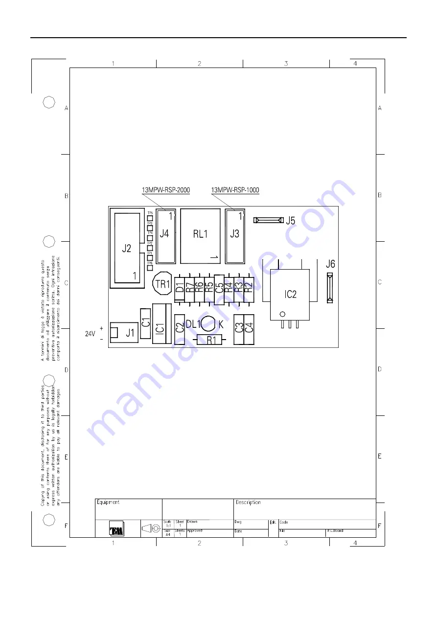
Page 81: ... 1 TP2 1 R5 C3 R2 J4 13MPW RSP 2000 13MPW RSP 1000 R6 C2 J3 R7 TR1 2 1 3 IC2 VCC 1 GND 2 VIOUT 3 IP 4 IP 5 C4 TP1 1 J1 1 2 RL1 3 2 4 8 9 7 1 10 R1 TP3 1 R3 IC1 3 2 1 I C O J2 1 3 5 7 9 2 4 6 8 10 J5 1 2 C5 TP6 1 D1 2 1 24V 1 3 5 7 9 2 4 6 8 10 1 3 5 7 9 2 4 6 8 10 11 12 11 12 13M31810 RF Current Amplifier Sensor Part Placement Layout ...

Page 82: ...TEM A07EXXXX 1 Unit Transmitters Page 82 Parts Placement ST AF 33336 02 09 14 13M31810 Current Sensor G3181 1 13M31810 Part list ...

Page 83: ...TEM A07EXXXX 1 Unit Transmitters Page 83 ...

Page 84: ...TEM A07EXXXX 1 Unit Transmitters Page 84 RF CURRENT AMPLIFIER SENSOR MODULE 13M32110 2019 Universal Version ...

Page 85: ...TEM A07EXXXX 1 Unit Transmitters Page 85 13M32110 Universal RF Current Amplifier Sensor Schematic Diagram ...

Page 86: ...TEM A07EXXXX 1 Unit Transmitters Page 86 13M32110 Universal RF Current Amplifier Sensor Pert Placement Layout ...

Page 87: ...TEM A07EXXXX 1 Unit Transmitters Page 87 13M32110 Part List ...

Page 88: ...TEM A07EXXXX 1 Unit Transmitters Page 88 RF20 50 100 200 250W POWER AMPLIFIER MODULE 13M3188B C ...

Page 89: ... 20 50 100 200 250W Power Amplifier Module Schematic Diagram Note1 The diagram below is a representative of the 13M3188 Family amplifier used also in other RF power levels Note2 difference between 13M3188B and 13M3188C is only in the RF LD MOS device model ...

Page 90: ...Unit Transmitters Page 90 13M31880B C RF 20 50 100 200 250W Power Amplifier Module Parts Placement Layout Note1 The diagram below is a representative of the 13M3188 Family amplifier used also in other RF power levels ...

Page 91: ...TEM A07EXXXX 1 Unit Transmitters Page 91 13M31880B Part list ...

Page 92: ...TEM A07EXXXX 1 Unit Transmitters Page 92 RF 300 400 500W POWER AMPLIFIER MODULE 13M72387B ...

Page 93: ... Power Amplifier Block Diagram 13M72387B SMA 13M 72050 M OD001 VD 20 48V 13M31790 M OD004 RF MODULE AMPLIFIER VS MODULATOR INTERFACE IN OUT BUS INTERFACE GATE VOLTAGE MEAS TEM PERATURE SENSOR FORWARD REFLECTED 13M 31760 MOD002 NTC GROUND 24V RF OUT FAN001 FAN002 RF IN N ...

Page 94: ...TEM A07EXXXX 1 Unit Transmitters Page 94 13M72387B Part list ...

Page 95: ...TEM A07EXXXX 1 Unit Transmitters Page 95 13M31760 FM HARMONICS FILTER DIRECTIONAL COUPLER Schematic Diagram ...

Page 96: ...TEM A07EXXXX 1 Unit Transmitters Page 96 13M31760 FM HARMONICS FILTER DIRECT COUPLER Parts Placement Layout ...

Page 97: ...TEM A07EXXXX 1 Unit Transmitters Page 97 13M31760 Part list ...

Page 98: ...TEM A07EXXXX 1 Unit Transmitters Page 98 13M720500 500W FM PALLET AMPLIFIER Schematic Diagram S T A4 1 1 ...

Page 99: ...TEM A07EXXXX 1 Unit Transmitters Page 99 13M720500 500W FM PALLET AMPLIFIER Parts Placement Layout S F A4 2 1 ...

Page 100: ...TEM A07EXXXX 1 Unit Transmitters Page 100 13M720500 Part list ...

Page 101: ...4 13M31790 Interfaccia Easy Controllo segnali Amplificatore G3179 0 C8 J1 1 3 5 7 9 2 4 6 8 10 JP8 V 2 1 JP4 NTC 2 1 JP5 NC1 2 1 C11 D1A 1 3 R2 R3 C3 C4 R1 JP1 UNB 2 1 C5 L6 C12 C13 C6 C14 JP2 1 2 JP10 1 2 JP11 GATE 2 1 L5 DZ2 1 3 JP7 1 2 C10 DZ1 1 3 JP12 RFL 2 1 C9 L7 L2 JP9 NC2 2 1 C15 L3 L1 C16 C1 L4 C2 JP6 1 2 C7 JP13 FWD 2 1 JP3 1 2 ...

Page 102: ...nsmitters Page 102 13M31790 EASY INTERFACE CONTROL SIGNAL AMPLIFIER Parts Placement Layout Parts Placement ST AF 33331 30 06 14 13M31790 Interfaccia Easy Controllo segnali Amplificatore G3179 0 Lato componenti Lato saldature ...

Page 103: ...TEM A07EXXXX 1 Unit Transmitters Page 103 13M31790 Part list ...

Page 104: ...TEM A07EXXXX 1 Unit Transmitters Page 104 RF HIGH GAIN 500W POWER AMPLIFIER MODULE 13M72387AHG OPT ...

Page 105: ... Amplifier Block Diagram 13M72387AHG SM A 13M31310AD M OD001 VD 20 48V 13M 31790 MOD004 RF MODULE AMPLIFIER INTERFACE IN OUT BUS INTERFACE GATE VOLTAGE M EAS TEMPERATURE SENSOR FORWARD REFLECTED 13M31321A MOD002 Q001 LD MOS M OD003 13MPWNID60S24 15 NTC GROUND 24V 15V ...

Page 106: ...TEM A07EXXXX 1 Unit Transmitters Page 106 13M72387AHG Part list ...

Page 107: ...6 8 10 JP8 V 2 1 JP4 NTC 2 1 JP5 NC1 2 1 C11 1n D1A BAV70 1 3 R2 1K8 R3 220R C3 1n C4 1n R1 18K JP1 UNB 2 1 C5 1n L6 1uH C12 100n C13 1n C6 1n C14 1n JP2 1 2 JP10 1 2 JP11 GATE 2 1 L5 1uH DZ2 4V7 1 3 JP7 1 2 C10 1n DZ1 4V7 1 3 JP12 RFL 2 1 C9 1n L7 1uH L2 1uH JP9 NC2 2 1 C15 1n L3 1uH L1 1uH C16 1n C1 1n L4 1uH C2 1n JP6 1 2 C7 1n JP13 FWD 2 1 JP3 1 2 MOD004 13M31790 13M31321A MOD002 TO ...

Page 108: ...TEM A07EXXXX 1 Unit Transmitters Page 108 13M31310AD RF High Gain Amplifier Input Board Parts Placement Layout A3 2 1 MOD003 13MPWNID60S24 15 GROUND 24V MOD004 13M31790 1 5 6 11 ST 33334 ...

Page 109: ...TEM A07EXXXX 1 Unit Transmitters Page 109 13M31310AD Part list ...

Page 110: ...TEM A07EXXXX 1 Unit Transmitters Page 110 13M31321A RF High Gain Amplifier Output Board Schematic Diagram S O A3 2 1 ...

Page 111: ...TEM A07EXXXX 1 Unit Transmitters Page 111 13M31321A RF High Gain Amplifier Output Board Part Placement Layout S O A3 2 1 ...

Page 112: ...TEM A07EXXXX 1 Unit Transmitters Page 112 13M31321A Part List ...

Page 113: ... 13M31790 Interfaccia Easy Controllo segnali Amplificatore G3179 0 C8 J1 1 3 5 7 9 2 4 6 8 10 JP8 V 2 1 JP4 NTC 2 1 JP5 NC1 2 1 C11 D1A 1 3 R2 R3 C3 C4 R1 JP1 UNB 2 1 C5 L6 C12 C13 C6 C14 JP2 1 2 JP10 1 2 JP11 GATE 2 1 L5 DZ2 1 3 JP7 1 2 C10 DZ1 1 3 JP12 RFL 2 1 C9 L7 L2 JP9 NC2 2 1 C15 L3 L1 C16 C1 L4 C2 JP6 1 2 C7 JP13 FWD 2 1 JP3 1 2 ...

Page 114: ...ransmitters Page 114 13M31790 RF High Gain Amplifier Easy Interface Part Placement Layout Parts Placement ST AF 33331 30 06 14 13M31790 Interfaccia Easy Controllo segnali Amplificatore G3179 0 Lato componenti Lato saldature ...

Page 115: ...TEM A07EXXXX 1 Unit Transmitters Page 115 13M31790 Part list ...

Page 116: ...XXX 1 Unit Transmitters Page 116 POWER SUPPLIES MODULES 13MPWRS7524 13MPWRS15024 on request 13MPWUSP22524 on request 13MPWSP48048 on request 13MPWRSP50048 13MPWRSP100048 13MPWRSP200048 on request 13MPWNID60S4824 ...

Page 117: ...TEM A07EXXXX 1 Unit Transmitters Page 117 13MPWRS7524 Exciter Services AC DC Power Supply Module ...

Page 118: ...TEM A07EXXXX 1 Unit Transmitters Page 118 13MPWRS15024 RF Power Amplifier AC DC Power Supply Module ...

Page 119: ...TEM A07EXXXX 1 Unit Transmitters Page 119 13MPWUSP22024 RF Power Amplifier AC DC Power Supply Module ...

Page 120: ...TEM A07EXXXX 1 Unit Transmitters Page 120 13MPWSP48048 RF Power Amplifier AC DC Power Supply Module ...

Page 121: ...TEM A07EXXXX 1 Unit Transmitters Page 121 13MPWRSP50048 RF Power Amplifier AC DC Power Supply Module ...

Page 122: ...TEM A07EXXXX 1 Unit Transmitters Page 122 13MPWRSP100048 RF Power Amplifier AC DC Power Supply Module ...

Page 123: ...TEM A07EXXXX 1 Unit Transmitters Page 123 13MPWRSP200048 RF Power Amplifier AC DC Power Supply Module ...

Page 124: ...TEM A07EXXXX 1 Unit Transmitters Page 124 13MPWNID60S4824 Internal RF Amplifier Services DC DC Power Supply ...

Page 125: ...TEM A07EXXXX 1 Unit Transmitters 13MAESEBU0 AES EBU TO L R DECODER MODULE ...

Page 126: ... C26 100n R8 10K L4 2u2 R29 270K C20 100n R23 10R R11 47K C4 100n DL1 ERROR J2 FLAT10 1 3 5 7 9 2 4 6 8 10 JP2 1 2 3 C37 22u25V C1 100n R13 47K R27 10K L3 2u2 IC2 CS4344 3 4 1 2 7 8 9 10 6 5 C21 10n R10 1K2 JP1 1 2 3 C7 1n C16 22u25V C22 22u25V IC3A TL072 3 2 1 R41 330R L1 2u2 JP7 C32 100n C35 100n C2 OPT C36 22u25V C33 100n C5 22u25V R28 470R R33 100K IC3B TL072 5 6 7 8 4 JP3 1 2 3 IC4 MC33269DT ...

Page 127: ...TEM A07EXXXX 1 Unit Transmitters 13MAESEBU0 AES EBU VS L R Part Placement Layout Parts Placement ST CF G3172 0 23 12 11 13MAESEBU0 SCHEDA INGR DIGITALE AES EBU Vs L R G3172 0 ...

Page 128: ...TEM A07EXXXX 1 Unit Transmitters 13MAESEBU0 Part list page 1 of 2 ...

Page 129: ...TEM A07EXXXX 1 Unit Transmitters 13MAESEBU0 Part list page 2 of 2 ...

Page 130: ...TEM A07EXXXX 1 Unit Transmitters Note ...

Page 131: ...TEM A07EXXXX 1 Unit Transmitters Note ...

Reviews: