AZ3s USER MANUAL
ST.TEC.054
32 / 60
4.5.2.
C
ONFIGURATIONS
To activate the digital input module, SET POINT SELECTOR must be set to two, or to three for the combined
use with analog inputs.
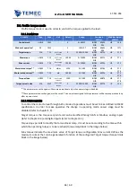
Every digital input edge can be configured as described in the following table.
Value of
selector
function
Operating mode*
0
Unused
-
1
Control word set to 15 (power stage enabled) and Target velocity set to the value
contained in Speed value 1
Profile velocity
2
Control word set to 15 (power stage enabled) and Target velocity set to the value
contained in Speed value 2
Profile velocity
3
Control word set to 15 (power stage enabled) and Target position set to the value
contained in Position value 1
Profile position
4
Control word set to 15 (power stage enabled) and Target position set to the value
contained in Position value 2
Profile position
5
Control word set to 15 (power stage enabled) and Target torque set to the value
contained in Torque value 1
Profile torque
6
Control word set to 15 (power stage enabled) and Target torque set to the value
contained in Torque value 2
Profile torque
7
Target velocity set to 0
Profile velocity
8
Target torque set to 0
Profile torque
9
Control word set to 6 (power stage disabled) and Target velocity set to 0
Profile velocity
10
Control word set to 6 (power stage disabled) and target torque set to 0
Profile torque
11
Position reset (Position actual value set to 0)
Position profile
12
Control word set to 15** (power stage enabled)
All
13
Control word set to 7** (power stage disabled)
All
14
Control word set to 6** (power stage disabled)
All
15
Control word set to 2** (power stage disabled)
All
16
Control word set to 0 (quick stop)** (power stage disabled)
All
17
Reset error
All
*refer to chapter 5
**To understand the effects of these operations refers to chapter 5.4
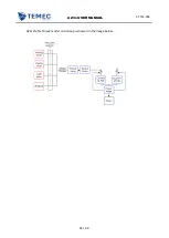
EXAMPLE: it is possible to enable the power stage and set the speed to 3000 with digital input 1,
disable the power stage with digital input 2, set the speed to 500 and enable the power stage at the
rising edge of digital input 3, set speed to 0 and disable power at the falling edge of digital input 3.
𝑆𝑝𝑒𝑒𝑑 𝑣𝑎𝑙𝑢𝑒 1 = 3000
𝐷𝐼1 𝑟𝑖𝑠𝑒 𝑠𝑒𝑙𝑒𝑐𝑡𝑜𝑟 = 1
𝐷𝐼2 𝑟𝑖𝑠𝑒 𝑠𝑒𝑙𝑒𝑐𝑡𝑜𝑟 = 14
𝑆𝑝𝑒𝑒𝑑 𝑣𝑎𝑙𝑢𝑒 2 = 500
𝐷𝐼3 𝑟𝑖𝑠𝑒 𝑠𝑒𝑙𝑒𝑐𝑡𝑜𝑟 1 = 2
𝐷𝐼3 𝑓𝑎𝑙𝑙 𝑠𝑒𝑙𝑒𝑐𝑡𝑜𝑟 1 = 9


