AZ3s USER MANUAL
ST.TEC.054
34 / 60
4.7.
Electromechanical brake
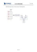
AZ3s could directly handle an electromechanical brake (refer to chapter 3.4.2).
4.7.1.
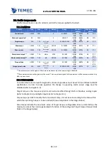
P
ARAMETERS
Variable
Type
Code
Unit
Default
Range
Can open
address
Modbus logical
address
AUX PWM OUT 1 SEL
UNS8
AXO1
-
0
0÷5
INDEX
SUB
204Eh
05h
HR
266L
BRAKE 1 MODE SEL
UNS8
AXO3
-
1
0÷100
INDEX
SUB
204Eh
07h
HR
267L
BRAKE 1 POW VALUE
UNS8
AXO4
%
100
0÷5
INDEX
SUB
204Fh
02h
HR
267H
Brake activation
COIL
DRF8
-
0
-
INDEX
SUB
2019h
(bit 7)
COIL
24
Brake value
COIL
DRF9
-
0
-
INDEX
SUB
2019h
(bit 8)
COIL
25
START
COIL
BKS1
-
0
-
INDEX
SUB
201Bh
(bit 0)
COIL
81
NOT READY TO SWITCH
ON
COIL
BKS2
-
0
-
INDEX
SUB
201Bh
(bit 1)
COIL
82
SWITCH ON DISABLED
COIL
BKS3
-
0
-
INDEX
SUB
201Bh
(bit 2)
COIL
82
READY TO SWITCH ON
COIL
BKS4
-
0
-
INDEX
SUB
201Bh
(bit 3)
COIL
83
SWITCHED ON
COIL
BKS5
-
0
-
INDEX
SUB
201Bh
(bit 4)
COIL
84
OPERATION ENABLED
COIL
BKS6
-
1
-
INDEX
SUB
201Bh
(bit 5)
COIL
85
QUICK STOP ACTIVE
COIL
BKS7
-
0
-
INDEX
SUB
201Bh
(bit 6)
COIL
86
FAULT
COIL
BKS8
-
0
-
INDEX
SUB
201Bh
(bit 7)
COIL
87
FAULT REACTION
ACTIVE
COIL
BKS9
-
0
-
INDEX
SUB
201Bh
(bit 8)
COIL
88
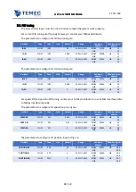
brake disengage time
UNS16
DRS3
ms
0
0÷65535
INDEX
SUB
204Fh
01h
HR
303
brake engage time
UNS16
DRS4
ms
0
0÷65535
INDEX
SUB
204Fh
02h
HR
304
4.7.2.
C
ONFIGURATION
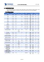
To use electromechanical brake through the drive, is first of all necessary to connect the power
output to the brake internal module through AUX PWM OUT 1 SEL.
𝐴𝑈𝑋 𝑃𝑊𝑀 𝑂𝑈𝑇 1 𝑆𝐸𝐿 = 1
Connect the internal brake handler to power output.
Brake value must be set with the duty cycle that commands the on state of the MOS that controls
the current flowing on the brake (open drain MOSFET).


