background image


   AZ3s USER MANUAL


                                        ST.TEC.054 


59 / 60 


9.


MAINTENANCE AND INSPECTION 


 Read carefully the safety precautions reported in chapter 1.7 before maintaining and inspecting 
the drive! 


Inspect  periodically  the  drive  to ensure  that  the environment  is  always  appropriate to  the  drive 
operation and to detect any sign of failure or malfunctioning.   


Visually check that the environment where the drive is placed is not subject to large amounts of 
dust, traces of water or other liquids, traces of condensate. If any of these elements is to be found, 
improve the environment or reconsider the positioning of the drive.   


Check    using    a    thermometer    that    the    environment    temperature    is    within    the    operation 
temperature limits. If it is not, improve the environment or reconsider the positioning of the drive.   


Check  that  the  load  current  and  the  board  temperature  is  not  much  different  from  the  values 
measured  during  a  normal  operating  cycle.  If  it  is  not,  check  that  the  mechanical  system  is  not 
subjected to high frictions or overloading.  


Check that all mounting screws and screw terminals are tightened firmly; if any of them is loose, 
tighten it.  

10.


 DISPOSAL 


 Read carefully the safety precautions reported in chapter 1.8 before disposing the drive! 


Contact a specialized agent in industrial disposal respecting to the local regulations. 


Summary of Contents for AZ3

Page 1: ...TeMec Drive Srl Via Beretta 1 42024 Castelnovo di Sotto RE Phone 39 0522 68 30 42 Fax 39 0522 68 81 31 P I 02614410351 ...

Page 2: ...tions 12 3 INSTALLATION AND WIRINGS 13 3 1 Installation environment 13 3 2 Mechanical installation 13 3 3 Mechanical drawings 13 3 4 Electrical connections 14 3 4 1 X1 Power 15 3 4 2 X2 connector 16 3 4 3 X3 connector 17 3 4 4 How to connect 18 4 DRIVE CONFIGURATIONS 22 4 1 Drive data 23 4 1 1 parameters 23 4 1 2 Configurations 23 4 2 Motor data 24 4 2 1 Parameters 24 4 2 2 Configurations 24 4 3 F...

Page 3: ...eters 36 4 8 2 Configuration 36 4 9 Braking behaviour 37 4 9 1 Parameters 37 4 9 2 Configurations 37 4 10 Emulated encoder 38 4 10 1 Parameters 38 4 10 2 Configurations 38 4 11 Motor thermistor 39 4 11 1 Parameters 39 4 11 2 Configurations 39 4 12 Torque limit 39 4 12 1 Parameters 39 4 12 2 Configurations 39 5 OPERATING MODES 40 5 1 Profile velocity mode 40 5 1 1 Parameters 40 5 1 2 Configuration ...

Page 4: ...rameters 46 5 4 2 Configurations 46 5 5 PID tuning 48 6 PARAMETERS TABLE 49 6 1 Holding registers 49 6 2 Input registers 53 6 3 Coils 54 7 ERRORS AND DIAGNOSTICS 55 7 1 Parameters 55 7 2 Diagnostic 56 8 TROUBLESHOOTING 57 8 1 Parameters 57 8 2 Problem solving 57 9 MAINTENANCE AND INSPECTION 59 10 DISPOSAL 59 ...

Page 5: ...raft 22 07 2020 mb Read carefully this manual before using the drive TeMec Drive reserves the right to change the information reported in this manual without prior notice because the product is in continuous evolution No part of this manual may be howsoever reproduced without previous consent by TeMec Drive ...

Page 6: ...erating limits Use the drive only in industrial application do not use it where a possible fault can cause serious injury to human life like nuclear plants aviation safety device entertainment and medical Use the drive only where a possible fault of the drive does not cause serious accidents or damages or use it only where safety equipment is applicable or a backup circuit device is provided outsi...

Page 7: ...n a proper insulating cabinet to avoid electric shock or other injury If the drive begins to emit smoke an unusual odour or unusual sounds immediately disconnect the power Continuous use of the drive in such a state may cause fire Call your TeMec Drive distributor for assistance and or repair Always turn the power off if the drive is not used for long time Leaks dust and other material may cause m...

Page 8: ...tall in any location where the drive could come into contact with water or other fluids This can result in electric shock or fire Operate under the environmental conditions prescribed in this instruction manual Operations under any other conditions may result in malfunction Install an emergency stop device that fits with system specifications The drive alone cannot stop operation immediately thus ...

Page 9: ...following steps must be performed before wiring o Turn off all input power o Wait at least 5 minutes and check to make sure that the on state LED is no longer lit o Use a tester that can measure DC voltage 60 V DC or more and check to make sure that the voltage to the DC main circuits across VDC and VDC is 45 V or less If these steps are not properly performed the wiring will cause electrical shoc...

Page 10: ... shock Do not touch the drive when the hands are wet Such action may result in electric shock If parameters are set incorrectly the drive may have some damage or unexpected movement Be sure to set the drive parameters correctly CAUTION Use a motor that conforms to the specifications of the drive and power supply If the motor being used does not conform to those specifications not only will the mot...

Page 11: ...LED is no longer lit o Use a tester that can measure DC voltage 60 V DC or more and check to make sure that the voltage to the DC main circuits across VDC and VDC is 45 V or less Performing an inspection without carrying out these steps first could lead to electric shock WARNING If you dispose of the drive have it done by a specialist in industry waste disposal If you dispose of the drive by yours...

Page 12: ...S POWER STAGE Supply voltage 24 V to 48 V DC maximum limits 20 V to 55 V DC Output current 17 A continuous 25 A Peak 2s Output power 800 W 1200 W 2s TECHINICAL CHARACTERISTICS Operating temperature 25 C 60 C Motor types Brushless AC Brushless DC DC motor Position feedback Hall Switches 120 incremental encoder CONTROL Control loops Torque current and speed Control modes Digital inputs analog input ...

Page 13: ...d installing location where there is the possibility of exposition to water large amounts of dust metallic fragments or corrosive gases Operate in areas where the temperature is within the limit temperatures Do not install in any location that can be subject to large amounts of vibrations Do not install in any location that contain any kind of flammable or explosive substances 3 2 Mechanical insta...

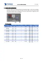
Page 14: ...AZ3s USER MANUAL ST TEC 054 14 60 3 4 Electrical connections During connection of terminals work with power disabled The image below shows AZ3 connectors ...

Page 15: ...current absorbed by the motor The counter part of this connector is a Molex 0768230322 to be used with the socket contacts Molex 1716920106 PIN DESCRIPTION 1 U M brushless motor U phase DC motor positive pole 2 V brushless motor V phase 3 W M brushless motor W phase DC motor negative pole 4 BRK RES Power output for braking resistor 5 VDC Positive supply and ground 6 VDC ...

Page 16: ...hermistor 5 Supply 5V DC 6 Ground 7 Power output for electromechanical brake 8 Incremental encoder CHA 9 Incremental encoder CHA 10 Incremental encoder CHB 11 Incremental encoder CHB 12 Incremental encoder CHZ 13 Incremental encoder CHZ 14 Internally connected to positive supply The counter part of this connector is a Molex 5016461400 to be used with the socket contacts Molex 5016471000 ...

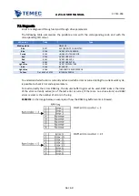
Page 17: ...tal input 4 9 Digital output 1 10 Ground 11 Analog input 1 12 RS485 for Modbus communication A 13 RS485 for Modbus communication B 14 UART for PC software communication TX 15 UART for PC software communication RX 16 Ground 17 Digital input 1 18 Digital input 3 19 Digital input 5 20 Digital output 2 21 Ground 22 Analog input 2 The counter part of this connector is a Molex 5016462200 to be used with...

Page 18: ... may damage the drive AZ3s has five digital inputs with the following schematic The input digital inputs voltage must be between 12 V and 48 V In the images below a connection examples is shown Through power output 4 of X1 the drive can manage a braking resistor without relay contactor The braking resistor must not be lower than 3 Ω ...

Page 19: ...ut relay contactor The current of the electromechanical brake must not exceed 1 A AZ3s has two digital outputs with the following schematic Do not exceed an input current of 100 mA Non observance of this specification may damage the drive In the images below a possible connection example ...

Page 20: ... 10 V and 10 V The input stage schematic of channels of incremental encoder is showed in the image below the encoder output differential voltage must be between 7 V and 12 V The input stage schematic of channels of Hall encoder is showed in the image below Refer to chapter 4 2 2 for Hall sequence ...

Page 21: ...es below an example of how connect PTC motor thermistor at AZ3s In order to properly connect the communication protocols note that termination resistor is not integrated in the circuit Contact your TeMec drive distributor for termination resistor ...

Page 22: ...all the following parameters using TeMec interface refer to TeMec interface manual During normal operation no error the drive LED blinks and has a white colour If the drive does not blink and has different colours it is in fault condition refer to chapter 7 Once the drive has been configured with the selected parameters these must be saved In order to save parameters set to 65766173h the parameter...

Page 23: ...36 0 1 0E6 INDEX SUB 2053h 02h HR 318 319 These parameters once changed must be saved The new value assigned to this parameter will become operational only after a power reset 4 1 2 CONFIGURATIONS Nominal current rms is the nominal current of the drive Alimentation power is the power absorbed by the drive with power stage disabled and V bus max is the maximum input voltage It is recommended to mai...

Page 24: ...NDEX SUB 2018h bit 0 COIL 1 Start phasing COIL DF2 0 INDEX SUB 2018h bit 1 COIL 2 auto phased motor COIL DF6 0 INDEX SUB 2018h bit 5 COIL 6 These parameters once changed must be saved The new value assigned to this parameter will become operational only after a power reset 4 2 2 CONFIGURATIONS It is necessary to set to 1 Motor type in order to control DC motor Motor type can be set to all the othe...

Page 25: ...cement between U phase rising edge and zero mark of 180 3 14 rad it is sufficient to set Encoder phase displacement to 3 14 AZ3s can perform an auto phasing routine for motors with incremental encoder with Hall Prior to start with the auto phasing routines disconnect the motor from the load and if a brake is connected to the motor disengage it with directs control as described in chapter 4 7 Facto...

Page 26: ... UNS32 FS10 8192 0 400000 INDEX SUB 608Fh 01h HR 107 108 Velocity factor numerator S16 FS11 60 0 32767 INDEX SUB 6094h 01h HR 109 Velocity factor denominator S16 FS12 1 0 32767 INDEX SUB 6094h 02h HR 110 Polarity UNS16 FS13 0 0 65536 INDEX SUB 607Eh HR 111 These parameters once changed must be saved The new value assigned to this parameter will become operational only after a power reset 4 3 2 CON...

Page 27: ...f 11 5 user unit 𝐹𝑒𝑒𝑑 𝑐𝑜𝑛𝑠𝑡𝑎𝑛𝑡 𝑓𝑒𝑒𝑑 23 𝐹𝑒𝑒𝑑 𝑐𝑜𝑛𝑠𝑡𝑎𝑛𝑡 𝑠ℎ𝑎𝑓𝑡 𝑟𝑒𝑣𝑜𝑙𝑢𝑡𝑖𝑜𝑛𝑠 2 𝐺𝑒𝑎𝑟 𝑟𝑎𝑡𝑖𝑜 𝑓𝑎𝑐𝑡𝑜𝑟 23 2 It is not possible to write directly 11 5 in Feed constant feed because the type of this parameter is unsigned Use Velocity encoder resolution motor revolutions and Velocity encoder resolution increments per second in order to calculate the velocity encoder resolutions 𝑉𝑒𝑙𝑜𝑐𝑖𝑡𝑦 𝑒𝑛𝑐𝑜𝑑𝑒𝑟 𝑟𝑒𝑠𝑜𝑙𝑢𝑡𝑖𝑜𝑛 𝑉𝑒𝑙𝑜𝑐𝑖...

Page 28: ...AMPLE if the user want to use rpm instead of rps Velocity factor numerator must be set to 60 and Velocity factor denominator must be set to 1 If different units of measure between position measurement and velocity measurement are needed the advice is to set before feed constant for reach the desired position unit of measure and then with Velocity factor numerator and Velocity factor denominator ad...

Page 29: ...0E9 INDEX SUB HR 260 261 AI Mult 2 FLOAT AI10 0 9 1 0E9 1 0E9 INDEX SUB HR 262 263 AI filter time UNS32 AI11 0 1 ms 10 0 200000 INDEX SUB HR 264 265 SET POINT SELECTOR S16 DD3 0 0 10 INDEX SUB 2038h HR 63 4 4 2 CONFIGURATIONS To activate the analog input module SET POINT SELECTOR must be set to 1 or to 3 for the combined use with digital inputs The adaptation of the analogic inputs in order to gen...

Page 30: ...g input to the preferred variable 0 unused 1 Target velocity refer to chapter 5 1 3 Target position refer to chapter 5 2 4 Target torque refer to chapter 5 3 EXAMPLE in order to control the speed of the motor through the analog input 1 from 1500 rpm to 1500 rpm with an input voltage variable form 10V to 10V the analog input variables must be configured as follow 𝑆𝑒𝑙𝑒𝑐𝑡𝑜𝑟 1 1 𝑈𝑠𝑒𝑟 𝑟𝑎𝑛𝑔𝑒 1 3000 𝑂𝑓𝑓𝑠...

Page 31: ...HR 320L DI1 fall selector UNS8 DI2 0 0 255 INDEX SUB 2047h 02h HR 320H DI2 rise selector UNS8 DI3 0 0 255 INDEX SUB 2047h 03h HR 321L DI2 fall selector UNS8 DI4 0 0 255 INDEX SUB 2047h 04h HR 321H DI3 rise selector UNS8 DI5 0 0 255 INDEX SUB 2047h 05h HR 322L DI3 fall selector UNS8 DI6 0 0 255 INDEX SUB 2047h 06h HR 322H DI4 rise selector UNS8 DI7 0 0 255 INDEX SUB 2047h 07h HR 323L DI4 fall selec...

Page 32: ...nd Target torque set to the value contained in Torque value 2 Profile torque 7 Target velocity set to 0 Profile velocity 8 Target torque set to 0 Profile torque 9 Control word set to 6 power stage disabled and Target velocity set to 0 Profile velocity 10 Control word set to 6 power stage disabled and target torque set to 0 Profile torque 11 Position reset Position actual value set to 0 Position pr...

Page 33: ...address Modbus logical address Output 1 selector UNS8 OF1 0 0 255 INDEX SUB 204Eh 02h HR 187L Output 2 selector UNS8 OF2 0 0 255 INDEX SUB 204Eh 03h HR 187H 4 6 2 CONFIGURATIONS Through Output 1 selector and Output 2 selector is possible to choice which feedback monitor connect to the output 0 unused 1 output set to 1 if drive works properly and to 0 in case of fault 2 output set to 1 when positio...

Page 34: ...bit 2 COIL 82 READY TO SWITCH ON COIL BKS4 0 INDEX SUB 201Bh bit 3 COIL 83 SWITCHED ON COIL BKS5 0 INDEX SUB 201Bh bit 4 COIL 84 OPERATION ENABLED COIL BKS6 1 INDEX SUB 201Bh bit 5 COIL 85 QUICK STOP ACTIVE COIL BKS7 0 INDEX SUB 201Bh bit 6 COIL 86 FAULT COIL BKS8 0 INDEX SUB 201Bh bit 7 COIL 87 FAULT REACTION ACTIVE COIL BKS9 0 INDEX SUB 201Bh bit 8 COIL 88 brake disengage time UNS16 DRS3 ms 0 0 ...

Page 35: ...coil is set to 0 in the corresponding state of the ds402 brake is engaged For example if the DS402 state machine is in operation enabled state and OPERATION ENABLED BKS6 coil is set to 1 then the brake is disinserted In this configuration brake disengage time and brake engage time are not used If BRAKE 1 MODE SEL is set to 2 brake is engaged and disengaged in the same condition of the case BRAKE 1...

Page 36: ...URATION At the start up of AZ3s when power is provided to the drive three possible DS402 states refer to chapter 5 4 can be reached in function of the state of Ready to switch on is reached at start up and Operation enabled is reached at start up If no one of this flags are set to 1 then at the start up the drive reaches the DS402 state Switch on disabled When Ready to switch on is reached at star...

Page 37: ... become operational only after a power reset 4 9 2 CONFIGURATIONS AZ3s takes care to limit the braking in order to avoid that the engine regenerates more energy than can be dissipated In order to protect the drive is necessary that the following data are correctly inserted Drive data V bus max it is the maximum value of tension that can be reached by the drive This value must be set in function of...

Page 38: ...𝑛𝑔 𝑟𝑒𝑠𝑖𝑠𝑡𝑜𝑟 𝑣𝑎𝑙𝑢𝑒 10 𝐵𝑟𝑎𝑘𝑖𝑛𝑔 𝑟𝑒𝑠𝑖𝑠𝑡𝑜𝑟 𝑚𝑎𝑥 𝑝𝑜𝑤𝑒𝑟 600 4 10 Emulated encoder AZ3s can provide the encoder emulated signal as output 4 10 1 PARAMETERS Variable Type Code Unit Default Range Can open address Modbus logical address Encoder feedback mode UNS8 EFM1 0 0 255 INDEX SUB 204Eh 04h HR 188L These parameters once changed must be saved The new value assigned to this parameter will become operationa...

Page 39: ...mit In speed mode and in position mode is possible to check the maximum torque supplied by the drive 4 12 1 PARAMETERS Variable Type Code Unit Default Range Can open address Modbus logical address Torque limit on COIL DF15 0 INDEX SUB 2018h bit 14 COIL 23 Torque limit FLOAT TF1 50 0 INDEX SUB 2009h 00h HR 161 Motor rated torque UNS32 TC4 mNm 2300 0 1 0E9 INDEX SUB 6076h HR 273 274 Motor rated curr...

Page 40: ...CM4 User units 0 2 0E6 2 0E6 INDEX SUB 60FFh 00h HR 158 159 Profile acceleration UNS32 SF2 Speed user units s 1000 0 2 0E6 INDEX SUB 6083h 00h HR 87 88 Profile deceleration UNS32 PRF1 Speed user units s 1000 0 2 0E6 INDEX SUB 6084h 00h HR 40 41 Invert speed feedback COIL DF7 0 INDEX SUB 2018h bit 6 COIL 7 Max profile velocity UNS32 PC7 User units 3000 0 2 0E6 INDEX SUB 607Fh 00h HR 289 290 Velocit...

Page 41: ... in the image below they must be set according to the time within which the operating speed is to be reached Velocity actual value is the feedback of the actual velocity Setting Invert speed feedback to 1 it is possible to invert the value read in Velocity actual value AZ3s Profile velocity mode control loop is showed in the image below ...

Page 42: ...289 290 Profile velocity UNS32 PC7 1000 0 2 0E6 INDEX SUB 6081h 00h HR 291 292 Position actual value S32 MV5 0 2 E9 2 0E9 INDEX SUB 6064h 00h IR 121 122 This parameter once changed will become operational only when power stage is disabled 5 2 2 CONFIGURATIONS To control the shaft position through AZ3s mode of operations must be set to 1 as defined in DS402 specification Target position is the posi...

Page 43: ...AZ3s USER MANUAL ST TEC 054 43 60 AZ3s Profile position mode control loop is showed in the image below ...

Page 44: ...torque 0 10000 10000 INDEX SUB 6077h IR 116 This parameter once changed will become operational only when power stage is disabled These parameters once changed must be saved The new value assigned to this parameter will become operational only after a power reset 5 3 2 CONFIGURATIONS To control the motor torque through AZ3s mode of operations must be set to 4 as defined in DS402 specification In o...

Page 45: ...AZ3s USER MANUAL ST TEC 054 45 60 AZ3s Profile Torque mode control loop is showed in the image below ...

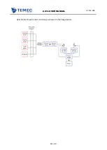
Page 46: ...ws transition in the image below Control word DISABLE_VOLTAGE_CODE 0 blue transitions in the image below Control word QUICK_STOP_CODE 2 orange transition in the image below Control word DISABLE_OP_CODE 7 green transitions in the image below Control word ENABLE_OP_CODE 15 yellow transitions in the image below AUTOMATIC TRANSITION black transitions in the image below Operation enable is the only sta...

Page 47: ...rd DS402 state machine xxxx xxxx x0xx 0000 Not ready to switch on xxxx xxxx x1xx 0000 Switch on disabled xxxx xxxx x01x 0001 Ready to switch on xxxx xxxx x01x 0011 Switched on xxxx xxxx x01x 0111 Operation enabled xxxx xxxx x00x 0111 Quick stop active xxxx xxxx x0xx 1111 Fault reaction active xxxx xxxx x0xx 1000 Fault ...

Page 48: ... 24 25 IQ KI FLOAT IQP2 200 0 1 0E21 1 0E21 INDEX SUB 2030h HR 26 27 IQ KD FLOAT IQP1 0 1 0E21 1 0E21 INDEX SUB 2031h HR 28 29 For speed PID and position PID tuning contact your TeMec distributor or use TeMec interface refer to TeMec interface manual The parameters to configure for speed loop tuning are Variable Type Code Unit Default Range Can open address Modbus logical address SPEED KP FLOAT SP...

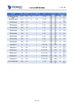
Page 49: ...LOAT SP1 0 1 0E21 1 0E21 INDEX SUB 2034h HR 38 39 Profile deceleration UNS32 PRF1 Speed user units s 1000 0 2 0E6 INDEX SUB 6084h 00h HR 40 41 V bus max FLOAT DD1 V 60 0 100 INDEX SUB 203Dh HR 60 61 ENCODER TYPE UNS16 DD2 0 0 10 INDEX SUB 2039h HR 62 SET POINT SELECTOR S16 DD3 0 0 10 INDEX SUB 2038h HR 63 MOTOR POLES PAIR UNS16 DD5 4 0 16 INDEX SUB 203Ah HR 65 Nominal current rms FLOAT IC1 A 30 10...

Page 50: ...E6 2 0E6 INDEX SUB 60FFh HR 158 159 TDI CW mode UNS8 SCM1 0 0 255 INDEX SUB 204Eh 01h HR 173L Motor type UNS16 MTY1 10 0 65535 INDEX SUB 6402h HR 176 Encoder phase displacement FLOAT PHC3 rad 3 14 6 28 6 28 INDEX SUB 2052h 03h HR 185 186 Output 1 selector UNS8 OF1 0 0 255 INDEX SUB 204Eh 02h HR 187L Output 2 selector UNS8 OF2 0 0 255 INDEX SUB 204Eh 03h HR 187H Encoder feedback mode UNS8 EFM1 0 0 ...

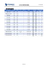
Page 51: ...sition S32 PC1 0 1 0E18 1 0E18 INDEX SUB 607Ah HR 279 280 Min position range limit S32 PC2 100000 1 0E18 1 0E18 INDEX SUB 607Bh 02h HR 281 282 Max position range limit S32 PC3 100000 1 0E18 1 0E18 INDEX SUB 607Bh 01h HR 283 284 Soft min position limit S32 PC4 0 1 0E18 1 0E18 INDEX SUB 607Dh 01h HR 285 286 Soft max position limit S32 PC5 0 1 0E18 1 0E18 INDEX SUB 607Dh 02h HR 287 288 Max profile ve...

Page 52: ...321H DI3 rise selector UNS8 DI5 0 0 255 INDEX SUB 2047h 05h HR 322L DI3 fall selector UNS8 DI6 0 0 255 INDEX SUB 2047h 06h HR 322H DI4 rise selector UNS8 DI7 0 0 255 INDEX SUB 2047h 07h HR 323L DI4 fall selector UNS8 DI8 0 0 255 INDEX SUB 2047h 08h HR 323H Speed value 1 S32 DI9 0 1 0E9 1 0E9 INDEX SUB 2048h HR 324 325 Speed value 2 S32 DI10 0 1 0E9 1 0E9 INDEX SUB 2049h HR 326 327 Position value 1...

Page 53: ...EX SUB 205Bh 01h IR 55 Error code 3 UNS16 DRL3 0 0 65535 INDEX SUB 205Ch 01h IR 62 Error code 4 UNS16 DRL4 0 0 65535 INDEX SUB 205Dh 01h IR 69 Error code 5 UNS16 DRL5 0 0 65535 INDEX SUB 205Eh 01h IR 76 Error code 6 UNS16 DRL6 0 0 65535 INDEX SUB 205Fh 01h IR 83 Error code 7 UNS16 DRL7 0 0 65535 INDEX SUB 2060h 01h IR 90 Error code 8 UNS16 DRL8 0 0 65535 INDEX SUB 2061h 01h IR 97 Torque actual val...

Page 54: ...19 Brake activation COIL DRF8 0 INDEX SUB 2019h bit 7 COIL 24 Brake value COIL DRF9 0 INDEX SUB 2019h bit 8 COIL 25 EEPROM autophasing data cleaning COIL DRF11 0 INDEX SUB 2019h bit 10 COIL 27 EEPROM parameters cleaning COIL DRF12 0 INDEX SUB 2019h bit 11 COIL 28 EEPROM total cleaning COIL DRF13 0 INDEX SUB 2019h bit 12 COIL 29 START COIL BKS1 0 INDEX SUB 201Bh bit 0 COIL 81 NOT READY TO SWITCH ON...

Page 55: ...ge Can open address Modbus logical address RAM errors counter UNS8 DLH4 0 0 255 INDEX SUB 2057h 06h IR 39L RAM index UNS8 DLH5 0 0 255 INDEX SUB 2057h 07h IR 39H Error code 1 UNS16 DRL1 0 0 65535 INDEX SUB 205Ah 01h IR 48 Error code 2 UNS16 DRL2 0 0 65535 INDEX SUB 205Bh 01h IR 55 Error code 3 UNS16 DRL3 0 0 65535 INDEX SUB 205Ch 01h IR 62 Error code 4 UNS16 DRL4 0 0 65535 INDEX SUB 205Dh 01h IR 6...

Page 56: ...lar buffer logic must be used RAM index is the index of the error currently active or of the last error occurred if there are no active errors and RAM errors counter is the number of errors in the log EXAMPLE In the image below an example of how the RAM log buffer works is showed LED colour Code Type Blinking white DRIVE OK Blue 8257 ENCODER NOT CONNECTED Blue 8258 OVER VOLTAGE ERROR Purple 8259 U...

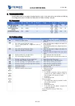
Page 57: ...heck the section and length of the power supply cables 8260 8261 8262 Mechanical obstacle or too high friction Errors in the wiring of the motors Check that motor load is not blocked Check that the motor is correctly connected to the drive 8263 The drive is working over its power capabilities The drive cannot dissipate enough heat Reduce the service of the motor Check that the drive is installed c...

Page 58: ...ration If the error persist o Set EEPROM total cleaning operation possible also via TeMec Interface o Reset Drive o Reconfigure the drive o If the motor was auto phased re execute the autophasing operation If error still persist contact you TeMec Drive distributor 24705 24732 EEPROM corrupted Follow this operation o Restart the drive If the error persist o Set EEPROM total cleaning operation possi...

Page 59: ... or reconsider the positioning of the drive Check using a thermometer that the environment temperature is within the operation temperature limits If it is not improve the environment or reconsider the positioning of the drive Check that the load current and the board temperature is not much different from the values measured during a normal operating cycle If it is not check that the mechanical sy...

Page 60: ...AZ3s USER MANUAL ST TEC 054 60 60 TeMec Drive Srl Via Beretta 1 42024 Castelnovo di Sotto RE Phone 39 0522 68 30 42 Fax 39 0522 68 81 31 P I 02614410351 ...

Reviews: